FRONT AXLE HUB > ON-VEHICLE INSPECTION

for Preparation Click here


NOTICE:
When the brake pedal is first depressed after replacing the brake pads or pushing back the disc brake piston, DTC C1214 may be output. As there is no malfunction, clear the DTC.

HINT:
  1. Use the same procedure for the RH side and LH side.
  2. The procedure listed below is for the LH side.


1. PRECAUTION

NOTICE:
After turning the power switch off, waiting time may be required before disconnecting the cable from the negative (-) auxiliary battery terminal. Therefore, make sure to read the disconnecting the cable from the negative (-) auxiliary battery terminal notices before proceeding with work (Click here).


2. DISABLE BRAKE CONTROL
  1. Wait at least 2 minutes after the power switch off.
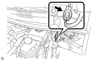
    NOTICE:
    When the brake pedal is depressed or the door courtesy switch is turned on even if the power switch is off, the brake control system activates. Therefore do not depress the brake pedal or open/close the doors until the reservoir level switch connector is disconnected.


    C232355
  1. Disconnect the reservoir level switch connector with the parking brake applied.

  1. Disconnect the cable from the negative (-) auxiliary battery terminal (Click here).

  1. Depress the brake pedal 40 times or more to return all the fluid in the accumulator back to the reservoir.

  1. Check that the brake pedal can not be further depressed.

  1. Release the parking brake.


3. REMOVE FRONT WHEEL


4. SEPARATE FRONT DISC BRAKE CALIPER ASSEMBLY
  1. Remove the 2 bolts and separate the front disc brake caliper assembly.

    NOTICE:
    Use wire or an equivalent tool to keep the front disc brake caliper assembly from hanging down by the flexible hose.


5. REMOVE FRONT DISC


    C205538E03
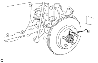
  1. Put matchmarks on the disc and the axle hub.
    Text in Illustration 
    *a
    Matchmark

  1. Remove the front disc.


6. INSPECT FRONT AXLE HUB BEARING LOOSENESS


    C205611
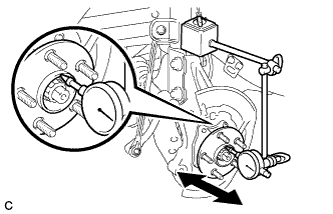
  1. Using a dial indicator, check for looseness near the center of the front axle hub sub-assembly.

    Maximum looseness:
    0.05 mm (0.00197 in.)

    NOTICE:
    1. Ensure that the dial indicator is set perpendicular to the measurement surface.
    2. Keep the magnet of the dial indicator away from the front speed sensor.

    HINT:
    If the looseness exceeds the maximum, replace the front axle hub sub-assembly.


7. INSPECT FRONT AXLE HUB RUNOUT


    C205610
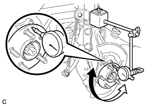
  1. Using a dial indicator, check for runout on the surface of the front axle hub sub-assembly outside the front hub bolt.

    Maximum runout:
    0.05 mm (0.00197 in.)

    NOTICE:
    1. Ensure that the dial indicator is set perpendicular to the measurement surface.
    2. Keep the magnet of the dial indicator away from the front speed sensor.

    HINT:
    If the runout exceeds the maximum, replace the front axle hub sub-assembly.


8. INSTALL FRONT DISC


    C205538E04
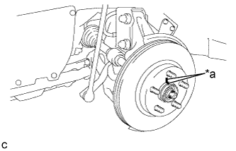
  1. Align the matchmarks of the disc and axle hub, and install the disc.
    Text in Illustration 
    *a
    Matchmark

    NOTICE:
    When replacing the disc with a new one, select the installation position where the front disc has minimal runout.


9. INSTALL FRONT DISC BRAKE CALIPER ASSEMBLY
  1. Install the front disc brake caliper assembly to the steering knuckle with the 2 bolts.

    Torque:
    137 N*m{ 1394 kgf*cm , 101 ft.*lbf }

    NOTICE:
    Do not twist the flexible hose when installing the front disc brake caliper assembly.


10. INSTALL FRONT WHEEL

Torque:
103 N*m{ 1050 kgf*cm , 76 ft.*lbf }


11. CONNECT CABLE TO NEGATIVE AUXILIARY BATTERY TERMINAL
  1. Connect the cable to the negative (-) auxiliary battery terminal (Click here).

  1. Connect the reservoir level switch connector.

  1. Clear the DTCs (Click here).