AIR CONDITIONING SYSTEM > Air Conditioning Control Panel Circuit |
| w/ Navigation System |
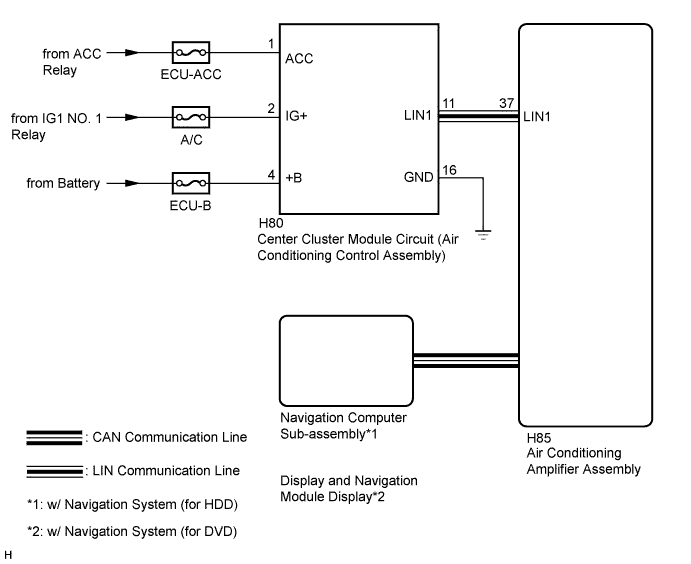
| w/o Navigation System |
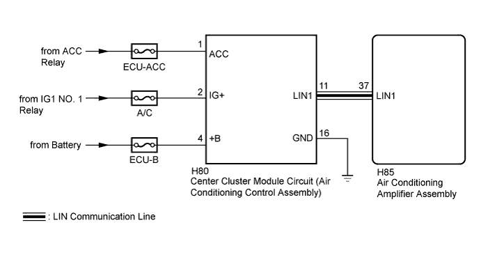
| 1.CONFIRM MODEL |
| Result | Proceed to |
| w/o Navigation System | A |
| w/ Navigation System | B |
|
| ||||
| A | |
 |
| 2.CHECK HARNESS AND CONNECTOR (POWER SOURCE, GROUND) |
Disconnect the center cluster module circuit (air conditioning control assembly) connector.
Measure the voltage according to the value(s) in the table below.
| Tester Connection | Condition | Specified Condition |
| H80-1 (ACC) - Body ground | Power switch off | Below 1 V |
| Power switch on (ACC) | 11 to 14 V | |
| H80-2 (IG+) - Body ground | Power switch off | Below 1 V |
| Power switch on (IG) | 11 to 14 V | |
| H80-4 (+B) - Body ground | Power switch off | 11 to 14 V |
Measure the resistance according to the value(s) in the table below.
| Tester Connection | Condition | Specified Condition |
| H80-16 (GND) - Body ground | Always | Below 1 Ω |
|
| ||||
| OK | |
|
| 3.CHECK HARNESS AND CONNECTOR (AIR CONDITIONING AMPLIFIER - CENTER CLUSTER MODULE CIRCUIT) |
Measure the resistance according to the value(s) in the table below.
| Tester Connection | Condition | Specified Condition |
| H80-11 (LIN1) - H85-37(LIN1) | Always | Below 1 Ω |
| H80-11 (LIN1) - Body ground | Always | 10 kΩ or higher |
|
| ||||
| OK | |
|
| 4.REPLACE CENTER CLUSTER MODULE CIRCUIT (AIR CONDITIONING CONTROL PANEL ASSEMBLY) |
Replace the center cluster module circuit (air conditioning control assembly) with a new or a known good one (Click here).
|
| ||||
| OK | ||
 | ||
| ||
| 5.CHECK NAVIGATION SYSTEM |
Check that the navigation system operates normally.
| Result | Proceed to |
| OK | A |
| NG (w/ Navigation System (for HDD)) | B |
| NG (w/ Navigation System (for DVD)) | C |
|
| ||||
|
| ||||
| A | |
|
| 6.CHECK HARNESS AND CONNECTOR (POWER SOURCE, GROUND) |
Disconnect the center cluster module circuit (air conditioning control assembly) connector.
Measure the voltage according to the value(s) in the table below.
| Tester Connection | Condition | Specified Condition |
| H80-1 (ACC) - Body ground | Power switch off | Below 1 V |
| Power switch on (ACC) | 11 to 14 V | |
| H80-2 (IG+) - Body ground | Power switch off | Below 1 V |
| Power switch on (IG) | 11 to 14 V | |
| H80-4 (+B) - Body ground | Power switch off | 11 to 14 V |
Measure the resistance according to the value(s) in the table below.
| Tester Connection | Condition | Specified Condition |
| H80-16 (GND) - Body ground | Always | Below 1 Ω |
|
| ||||
| OK | |
|
| 7.CHECK HARNESS AND CONNECTOR (AIR CONDITIONING AMPLIFIER - CENTER CLUSTER MODULE CIRCUIT) |
Measure the resistance according to the value(s) in the table below.
| Tester Connection | Condition | Specified Condition |
| H80-11 (LIN1) - H85-37(LIN1) | Always | Below 1 Ω |
| H80-11 (LIN1) - Body ground | Always | 10 kΩ or higher |
|
| ||||
| OK | |
|
| 8.REPLACE CENTER CLUSTER MODULE CIRCUIT (AIR CONDITIONING CONTROL ASSEMBLY) |
Replace the center cluster module circuit (air conditioning control assembly) with a new or a known good one (Click here).
|
| ||||
| OK | ||
| ||
| ||


