SFI SYSTEM > VC Output Circuit |
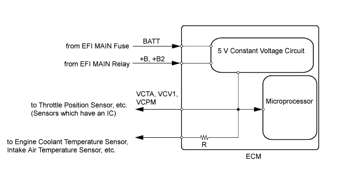
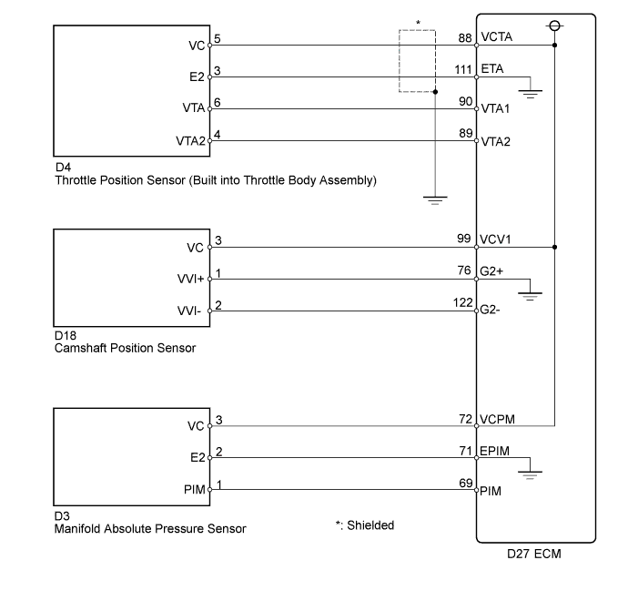
| 1.CHECK MIL |
Check that the Malfunction Indicator Lamp (MIL) illuminates when turning the power switch on (IG).
|
| ||||
| OK | ||
 | ||
| ||
| 2.CHECK CONNECTION BETWEEN INTELLIGENT TESTER AND ECM |
Connect the intelligent tester to the DLC3.
Turn the power switch on (IG).
Turn the tester on.
Check the communication between the intelligent tester and ECM.
| Result | Proceed to |
| Communication is not possible | A |
| Communication is possible | B |
|
| ||||
| A | |
 |
| 3.CHECK MIL (THROTTLE POSITION SENSOR) |
Disconnect the throttle position sensor connector.
Turn the power switch on (IG).
Check the MIL.
| Result | Proceed to |
| MIL does not illuminate | A |
| MIL illuminates | B |
|
| ||||
| A | |
|
| 4.CHECK MIL (CAMSHAFT POSITION SENSOR) |
Disconnect the camshaft position sensor connector.
Turn the power switch on (IG).
Check the MIL.
| Result | Proceed to |
| MIL does not illuminate | A |
| MIL illuminates | B |
|
| ||||
| A | |
|
| 5.CHECK MIL (MANIFOLD ABSOLUTE PRESSURE SENSOR) |
Disconnect the manifold absolute pressure sensor connector.
Turn the power switch on (IG).
Check the MIL.
| Result | Proceed to |
| MIL does not illuminate | A |
| MIL illuminates | B |
|
| ||||
| A | |
|
| 6.CHECK HARNESS AND CONNECTOR |
Disconnect the throttle position sensor connector.
Disconnect the camshaft position sensor connector.
Disconnect the manifold absolute pressure sensor connector.
Disconnect the ECM connector.
Measure the resistance according to the value(s) in the table below.
| Tester Connection | Condition | Specified Condition |
| D4-5 (VC) or D27-88 (VCTA) - Body ground | Always | 10 kΩ or higher |
| D18-3 (VC) or D27-99 (VCV1) - Body ground | Always | 10 kΩ or higher |
| D3-3 (VC) or D27-72 (VCPM) - Body ground | Always | 10 kΩ or higher |
|
| ||||
| OK | ||
| ||
| ||


