FRONT DOOR BELT MOULDING > INSTALLATION |
| 1. PRECAUTION |
| 2. INSTALL FRONT DOOR BELT MOULDING ASSEMBLY |
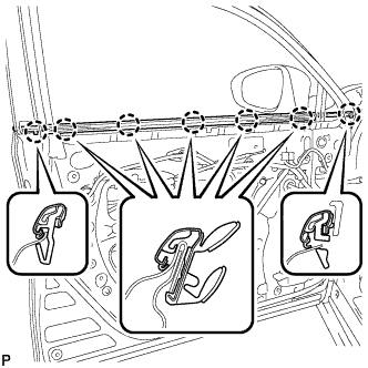 |
Engage the 7 claws to install the front door belt moulding assembly.
| 3. INSTALL FRONT DOOR FRONT LOWER FRAME UPPER COVER |
| Item | Temperature |
| Vehicle Body | 40 to 60°C (104 to 140°F) |
Clean the vehicle body surface.
Using a heat light, heat the vehicle body surface.
Remove the double-sided tape from the vehicle body.
Wipe off any tape adhesive residue with cleaner.
Install a new front door front lower frame upper cover.
Using a heat light, heat the vehicle body and a new front door front lower frame upper cover.
Remove the release paper from the front door front lower frame upper cover.
Engage the 2 clips and install the new front door front lower frame upper cover.
| 4. INSTALL FRONT DOOR GLASS RUN |
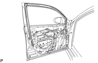 |
Install the front door glass run.
| 5. INSTALL FRONT DOOR GLASS SUB-ASSEMBLY |
Connect the cable to the negative (-) battery terminal.
Connect the power window regulator master switch assembly and move the front door glass sub-assembly so that the door glass bolts can be seen.
Disconnect the cable from the negative (-) battery terminal.
Disconnect the power window regulator master switch assembly.
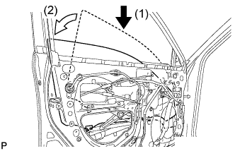 |
Insert the front door glass sub-assembly into the front door panel along the front door glass run as indicated by the arrows in the order shown in the illustration.
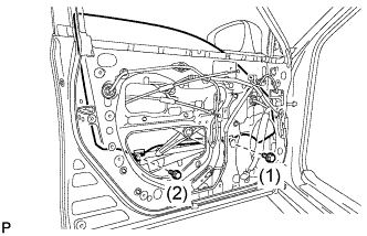 |
Install the front door glass sub-assembly with the 2 bolts.
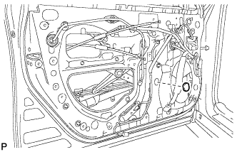 |
Install the grommet.
| 6. INSTALL FRONT DOOR SERVICE HOLE COVER |
Apply butyl tape to the front door panel.
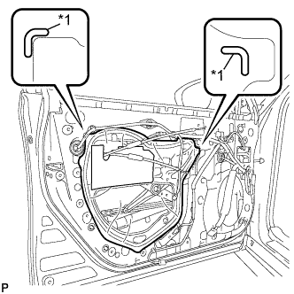 |
Pass the front door lock remote control cable assembly and front door inside locking cable assembly through a new front door service hole cover.
| *1 | Reference Point |
Attach the front door service hole cover according to the reference points on the front door panel.
| 7. INSTALL FRONT DOOR TRIM BRACKET (for Driver Side) |
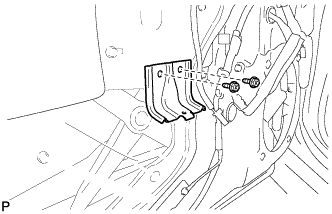 |
Install the front door trim bracket with the 2 screws.
| 8. INSTALL FRONT DOOR TRIM BRACKET (for Front Passenger Side) |
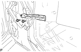 |
Install the front door trim bracket with the 2 screws.
| 9. INSTALL FRONT DOOR TRIM BOARD SUB-ASSEMBLY (for Driver Side) |
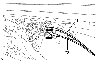 |
Connect the front door lock remote control cable assembly and front door inside locking cable assembly.
| *1 | Front Door Inside Locking Cable Assembly |
| *2 | Front Door Lock Remote Control Cable Assembly |
w/ Seat Position Memory System:
Connect the connector.
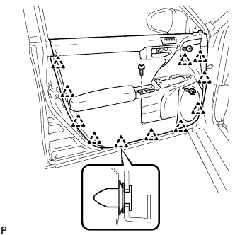 |
Engage the 11 clips and install the front door trim board sub-assembly.
Install the 2 screws.
Remove the protective tape.
| 10. INSTALL DOOR ARMREST COVER (for Driver Side) |
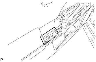 |
Install the door armrest cover.
| 11. INSTALL POWER WINDOW REGULATOR MASTER SWITCH ASSEMBLY WITH FRONT DOOR ARMREST BASE PANEL (for Driver Side) |
Connect the connector.
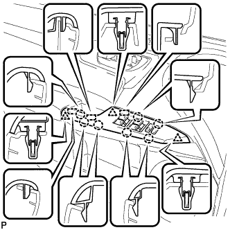 |
Engage the 2 guides, 3 clips and 7 claws, and install the power window regulator master switch assembly with front door armrest base panel.
| 12. INSTALL FRONT DOOR TRIM BOARD SUB-ASSEMBLY (for Front Passenger Side) |
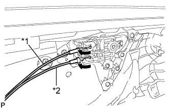 |
Connect the front door lock remote control cable assembly and front door inside locking cable assembly.
| *1 | Front Door Inside Locking Cable Assembly |
| *2 | Front Door Lock Remote Control Cable Assembly |
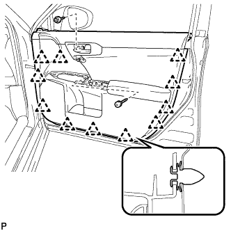 |
Engage the 11 clips and install the front door trim board sub-assembly.
Install the 3 screws.
Remove the protective tape.
| 13. INSTALL DOOR ASSIST GRIP ASSEMBLY (for Front Passenger Side) |
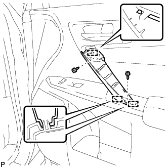 |
Engage the 3 guides and install the door assist grip assembly.
Install the 2 screws.
| 14. INSTALL DOOR ASSIST GRIP COVER (for Front Passenger Side) |
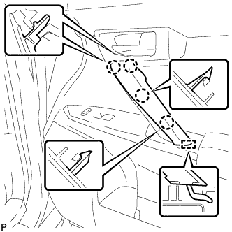 |
Engage the guide and 4 claws, and install a new door assist grip cover.
| 15. INSTALL POWER WINDOW REGULATOR SWITCH ASSEMBLY WITH FRONT DOOR ARMREST BASE PANEL (for Front Passenger Side) |
Connect the connector.
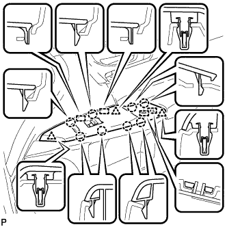 |
Engage the 4 guides, 3 clips and 8 claws, and install the power window regulator switch assembly with front door armrest base panel.
| 16. INSTALL FRONT DOOR LOWER FRAME BRACKET GARNISH |
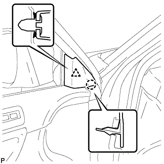 |
Engage the clip and claws, and install the front door lower frame bracket garnish.
| 17. INSTALL FRONT DOOR INSIDE HANDLE BEZEL PLUG |
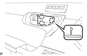 |
Engage the 3 claws and install the front door inside handle bezel plug.
| 18. CONNECT CABLE TO NEGATIVE BATTERY TERMINAL |
| 19. INSTALL REAR FLOOR BOARD UPPER NO. 3 PLATE |
Engage the 4 claws and 2 guides to install the rear floor board upper No. 3 plate.
| 20. INSTALL DECK FLOOR BOX RH |
Engage the 6 guides.
Install the deck floor box RH with the clip.
| 21. INSTALL REAR NO. 3 FLOOR BOARD |
Install the rear No. 3 floor board.
| 22. INSTALL REAR DECK FLOOR BOX |
Install the rear deck floor box.
| 23. INSTALL REAR NO. 2 FLOOR BOARD |
Install the rear No. 2 floor board.
| 24. INITIALIZE POWER WINDOW CONTROL SYSTEM |
