FRONT DOOR WINDOW FRAME MOULDING > INSTALLATION |
| 1. PRECAUTION |
| 2. INSTALL FRONT DOOR UPPER WINDOW FRAME MOULDING |
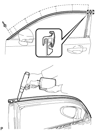 |
Engage the front door upper window frame moulding to the door frame.
Using an air riveter or hand riveter with a nose piece, install the front door upper window frame moulding with 8 new rivets.
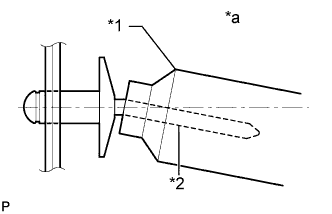 |
| *1 | Riveter |
| *2 | Mandrel |
| *a | Incorrect |
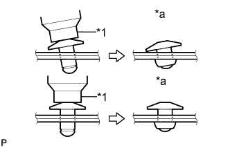 |
| *1 | Riveter |
| *a | Incorrect |
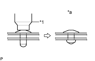 |
| *1 | Riveter |
| *a | Incorrect |
| 3. INSTALL FRONT DOOR REAR WINDOW FRAME MOULDING |
| Item | Temperature |
| Vehicle Body | 40 to 60°C (104 to 140°F) |
| Moulding | 20 to 30°C (68 to 86°F) |
Clean the vehicle body surface.
Using a heat light, heat the vehicle body surface.
Remove the double-sided tape from the vehicle body.
Wipe off any tape adhesive residue with cleaner.
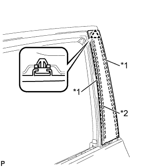 |
Install a new front door rear window frame moulding.
| *1 | Double-sided Tape |
| *2 | Caulking Sponge |
Using a heat light, heat the vehicle body and front door rear window frame moulding.
Remove the release paper from the face of the front door rear window frame moulding.
Install the front door rear window frame moulding with the clip.
| 4. INSTALL FRONT DOOR WEATHERSTRIP |
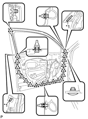 |
Engage the 20 clips and install a new front door weatherstrip.
| *1 | Double-sided Tape |
| 5. INSTALL FRONT DOOR CHECK ASSEMBLY |
Apply MP grease to the sliding areas of the front door check assembly.
Apply adhesive to the threads of the bolt.
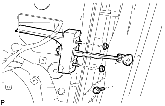 |
Install the front door check assembly with the bolt and 2 nuts.
| 6. INSTALL FRONT DOOR BELT MOULDING ASSEMBLY |
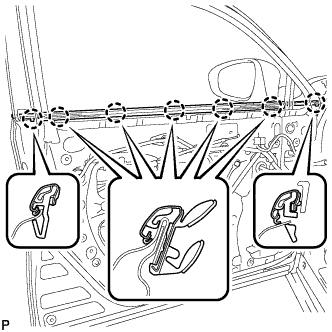 |
Engage the 7 claws to install the front door belt moulding assembly.
| 7. INSTALL FRONT DOOR FRONT LOWER FRAME UPPER COVER |
| Item | Temperature |
| Vehicle Body | 40 to 60°C (104 to 140°F) |
Clean the vehicle body surface.
Using a heat light, heat the vehicle body surface.
Remove the double-sided tape from the vehicle body.
Wipe off any tape adhesive residue with cleaner.
Install a new front door front lower frame upper cover.
Using a heat light, heat the vehicle body and a new front door front lower frame upper cover.
Remove the release paper from the front door front lower frame upper cover.
Engage the 2 clips and install the new front door front lower frame upper cover.
| 8. INSTALL FRONT DOOR GLASS RUN |
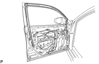 |
Install the front door glass run.
| 9. INSTALL FRONT DOOR GLASS SUB-ASSEMBLY |
Connect the cable to the negative (-) battery terminal.
Connect the power window regulator master switch assembly and move the front door glass sub-assembly so that the door glass bolts can be seen.
Disconnect the cable from the negative (-) battery terminal.
Disconnect the power window regulator master switch assembly.
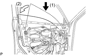 |
Insert the front door glass sub-assembly into the front door panel along the front door glass run as indicated by the arrows in the order shown in the illustration.
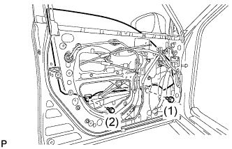 |
Install the front door glass sub-assembly with the 2 bolts.
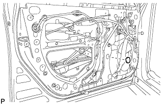 |
Install the grommet.
| 10. INSTALL FRONT DOOR SERVICE HOLE COVER |
Apply butyl tape to the front door panel.
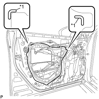 |
Pass the front door lock remote control cable assembly and front door inside locking cable assembly through a new front door service hole cover.
| *1 | Reference Point |
Attach the front door service hole cover according to the reference points on the front door panel.
| 11. INSTALL FRONT DOOR TRIM BRACKET (for Driver Side) |
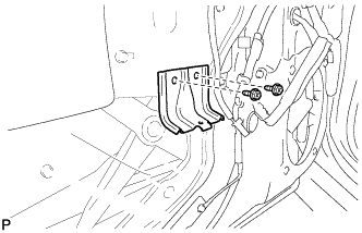 |
Install the front door trim bracket with the 2 screws.
| 12. INSTALL FRONT DOOR TRIM BRACKET (for Front Passenger Side) |
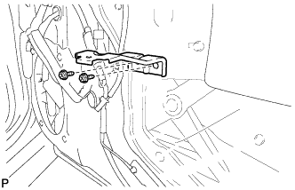 |
Install the front door trim bracket with the 2 screws.
| 13. INSTALL FRONT DOOR TRIM BOARD SUB-ASSEMBLY (for Driver Side) |
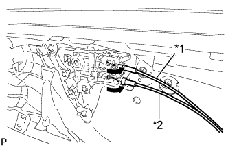 |
Connect the front door lock remote control cable assembly and front door inside locking cable assembly.
| *1 | Front Door Inside Locking Cable Assembly |
| *2 | Front Door Lock Remote Control Cable Assembly |
w/ Seat Position Memory System:
Connect the connector.
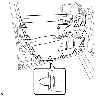 |
Engage the 11 clips and install the front door trim board sub-assembly.
Install the 2 screws.
Remove the protective tape.
| 14. INSTALL DOOR ARMREST COVER (for Driver Side) |
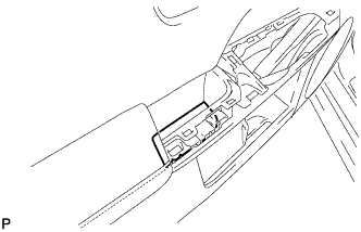 |
Install the door armrest cover.
| 15. INSTALL POWER WINDOW REGULATOR MASTER SWITCH ASSEMBLY WITH FRONT DOOR ARMREST BASE PANEL (for Driver Side) |
Connect the connector.
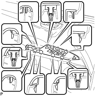 |
Engage the 2 guides, 3 clips and 7 claws, and install the power window regulator master switch assembly with front door armrest base panel.
| 16. INSTALL FRONT DOOR TRIM BOARD SUB-ASSEMBLY (for Front Passenger Side) |
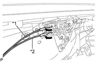 |
Connect the front door lock remote control cable assembly and front door inside locking cable assembly.
| *1 | Front Door Inside Locking Cable Assembly |
| *2 | Front Door Lock Remote Control Cable Assembly |
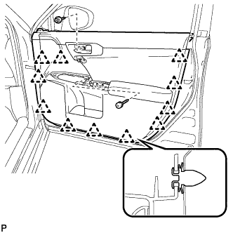 |
Engage the 11 clips and install the front door trim board sub-assembly.
Install the 3 screws.
Remove the protective tape.
| 17. INSTALL DOOR ASSIST GRIP ASSEMBLY (for Front Passenger Side) |
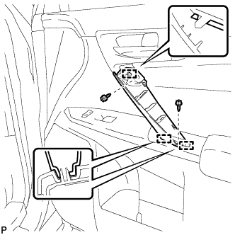 |
Engage the 3 guides and install the door assist grip assembly.
Install the 2 screws.
| 18. INSTALL DOOR ASSIST GRIP COVER (for Front Passenger Side) |
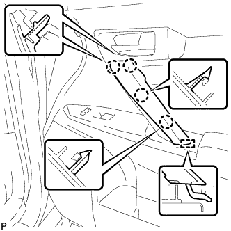 |
Engage the guide and 4 claws, and install a new door assist grip cover.
| 19. INSTALL POWER WINDOW REGULATOR SWITCH ASSEMBLY WITH FRONT DOOR ARMREST BASE PANEL (for Front Passenger Side) |
Connect the connector.
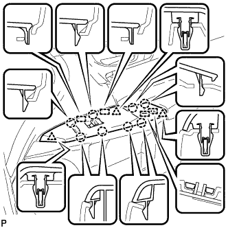 |
Engage the 4 guides, 3 clips and 8 claws, and install the power window regulator switch assembly with front door armrest base panel.
| 20. INSTALL FRONT DOOR LOWER FRAME BRACKET GARNISH |
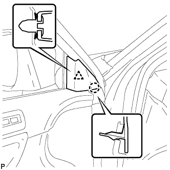 |
Engage the clip and claws, and install the front door lower frame bracket garnish.
| 21. INSTALL FRONT DOOR INSIDE HANDLE BEZEL PLUG |
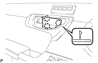 |
Engage the 3 claws and install the front door inside handle bezel plug.
| 22. CONNECT CABLE TO NEGATIVE BATTERY TERMINAL |
| 23. INSTALL REAR FLOOR BOARD UPPER NO. 3 PLATE |
Engage the 4 claws and 2 guides to install the rear floor board upper No. 3 plate.
| 24. INSTALL DECK FLOOR BOX RH |
Engage the 6 guides.
Install the deck floor box RH with the clip.
| 25. INSTALL REAR NO. 3 FLOOR BOARD |
Install the rear No. 3 floor board.
| 26. INSTALL REAR DECK FLOOR BOX |
Install the rear deck floor box.
| 27. INSTALL REAR NO. 2 FLOOR BOARD |
Install the rear No. 2 floor board.
| 28. INITIALIZE POWER WINDOW CONTROL SYSTEM |
