DTC    B1243    GSW Terminal Circuit Malfunction

for Preparation Click here


DESCRIPTION

If the collision door lock release function does not operate normally, or an open or short in the GSW input circuit of the main body ECU (multiplex network body ECU) is detected, DTC B1243 will be stored.

HINT:
If DTC B1243 is stored, the speed-sensitive automatic door lock function, shift-linked automatic door lock function, and collision door lock release function will be prohibited.


DTC No.
DTC Detection Condition
Trouble Area
B1243
A malfunction occurs in the GSW input circuit of the main body ECU (multiplex network body ECU).
  1. Main body ECU (multiplex network body ECU)
  2. Airbag sensor assembly
  3. Wire harness or connector

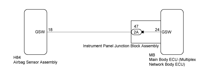
WIRING DIAGRAM


B193363E10


INSPECTION PROCEDURE

NOTICE:
After turning the power switch off, waiting time may be required before disconnecting the cable from the negative (-) auxiliary battery terminal. Therefore, make sure to read the disconnecting the cable from the negative (-) auxiliary battery terminal notices before proceeding with work (Click here).
1.CHECK DTC OUTPUT
  1. Clear the DTCs (Click here).

  1. Recheck for DTCs.

    OK:
    DTC B1243 is not output.


NG
Go to step 2
OK

USE SIMULATION METHOD TO CHECK (Click here)  

2.CHECK MAIN BODY ECU (MULTIPLEX NETWORK BODY ECU) (GSW VOLTAGE)
  1. Disconnect the cable from the negative (-) auxiliary battery terminal.

    CAUTION:
    Wait at least 90 seconds after disconnecting the cable from the negative (-) auxiliary battery terminal to disable the SRS system.

  1. Disconnect the airbag sensor assembly connector.

  1. Connect the cable to the negative (-) auxiliary battery terminal.


    B275903E01
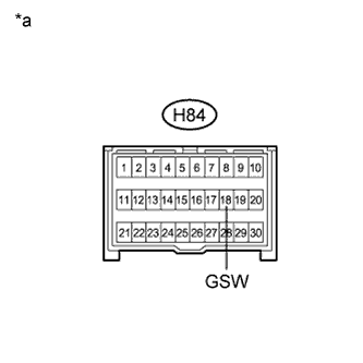
  1. Measure the voltage according to the value(s) in the table below.

    Standard Voltage:
    Tester Connection
    Condition
    Specified Condition
    H84-18 (GSW) - Body ground
    Power switch on (IG)
    4.5 to 5.5 V

    Text in Illustration 
    *a
    Front view of wire harness connector
    (to Airbag Sensor Assembly)

    NOTICE:
    Turning the power switch on (IG) with the airbag sensor assembly connector disconnected causes other DTCs to be stored. Clear the DTCs after performing this inspection.


NG
Go to step 5
OK


3.REPLACE AIRBAG SENSOR ASSEMBLY
  1. Disconnect the cable from the negative (-) auxiliary battery terminal.

    CAUTION:
    Wait at least 90 seconds after disconnecting the cable from the negative (-) auxiliary battery terminal to disable the SRS system.

  1. Replace the airbag sensor assembly (Click here).


NEXT


4.CHECK DTC OUTPUT
  1. Clear the DTCs (Click here).

  1. Recheck for DTCs.

    OK:
    DTC B1243 is not output.


NG
REPLACE MAIN BODY ECU (MULTIPLEX NETWORK BODY ECU) (Click here)
OK

END (AIRBAG SENSOR ASSEMBLY WAS DEFECTIVE) 

5.CHECK HARNESS AND CONNECTOR (AIRBAG SENSOR ASSEMBLY - INSTRUMENT PANEL JUNCTION BLOCK)
  1. Disconnect the cable from the negative (-) auxiliary battery terminal.

    CAUTION:
    Wait at least 90 seconds after disconnecting the cable from the negative (-) auxiliary battery terminal to disable the SRS system.

  1. Disconnect the airbag sensor assembly connector.

  1. Disconnect the instrument panel junction block connector.

  1. Measure the resistance according to the value(s) in the table below.

    Standard Resistance:
    Tester Connection
    Condition
    Specified Condition
    H84-18 (GSW) - 2A-47
    Always
    Below 1 Ω
    2A-47 - Body ground
    Always
    10 kΩ or higher


NG
REPAIR OR REPLACE HARNESS OR CONNECTOR
OK


6.INSPECT INSTRUMENT PANEL JUNCTION BLOCK ASSEMBLY
  1. Remove the instrument panel junction block assembly (Click here).


  1. Remove the main body ECU (multiplex network body ECU).
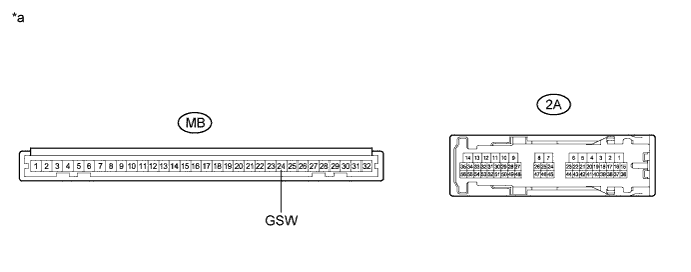

    B217444E16

  1. Measure the resistance according to the value(s) in the table below.

    Standard Resistance:
    Tester Connection
    Condition
    Specified Condition
    MB-24 (GSW) - 2A-47
    Always
    Below 1 Ω


    Text in Illustration 
    *a
    Component without harness connected
    (Instrument Panel Junction Block Assembly)
    -
    -


NG
REPLACE INSTRUMENT PANEL JUNCTION BLOCK ASSEMBLY (Click here)
OK

REPLACE MAIN BODY ECU (MULTIPLEX NETWORK BODY ECU) (Click here)