THEFT DETERRENT SYSTEM > Engine Hood Courtesy Switch Circuit |
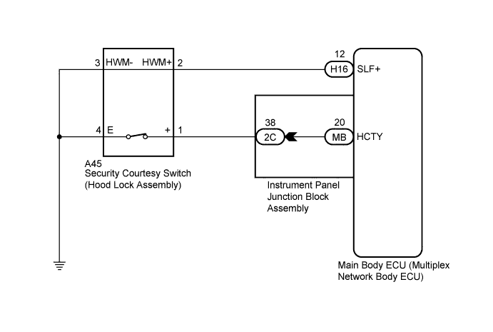
| 1.READ VALUE USING INTELLIGENT TESTER |
Connect the intelligent tester to the DLC3.
Turn the power switch on (IG).
Turn the intelligent tester on.
Enter the following menus: Body / Main Body / Data List.
According to the display on the intelligent tester, read the Data List.
| Tester Display | Measurement Item/Range | Normal Condition | Diagnostic Note |
| Hood Courtesy SW | Security courtesy switch signal/ON or OFF | ON: Engine hood open OFF: Engine hood closed | - |
|
| ||||
| OK | ||
 | ||
| ||
| 2.INSPECT INSTRUMENT PANEL JUNCTION BLOCK ASSEMBLY |
Disconnect the 2C instrument panel junction block assembly and MB main body ECU (multiplex network body ECU) connectors.
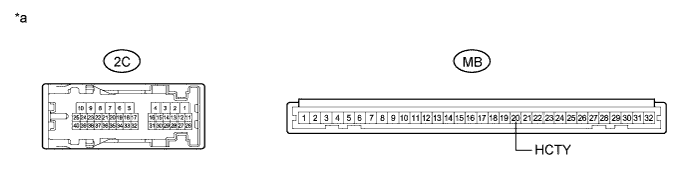
Measure the resistance according to the value(s) in the table below.
| Tester Connection | Condition | Specified Condition |
| 2C-38 - MB-20 (HCTY) | Always | Below 1 Ω |
| 2C-38 - Body ground | Always | 10 kΩ or higher |
| *a | Component without harness connected (Instrument Panel Junction Block Assembly) | - | - |
|
| ||||
| OK | |
 |
| 3.CHECK HARNESS AND CONNECTOR (INSTRUMENT PANEL JUNCTION BLOCK ASSEMBLY - SECURITY COURTESY SWITCH - BODY GROUND) |
Disconnect the A45 security courtesy switch (hood lock assembly) connector.
Measure the resistance according to the value(s) in the table below.
| Tester Connection | Condition | Specified Condition |
| A45-1 (+) - 2C-38 | Always | Below 1 Ω |
| A45-1 (+) - Body ground | Always | 10 kΩ or higher |
| A45-4 (E) - Body ground | Always | Below 1 Ω |
|
| ||||
| OK | |
|
| 4.CHECK HARNESS AND CONNECTOR (MAIN BODY ECU - SECURITY COURTESY SWITCH - BODY GROUND) |
Disconnect the H16 main body ECU (multiplex network body ECU) connector.
Measure the resistance according to the value(s) in the table below.
| Tester Connection | Condition | Specified Condition |
| A45-2 (HWM+) - H16-12 (SLF+) | Always | Below 1 Ω |
| A45-2 (HWM+) - Body ground | Always | 10 kΩ or higher |
| A45-3 (HWM-) - Body ground | Always | Below 1 Ω |
|
| ||||
| OK | |
|
| 5.INSPECT SECURITY COURTESY SWITCH (HOOD LOCK ASSEMBLY) |
Remove the hood lock assembly (Click here).
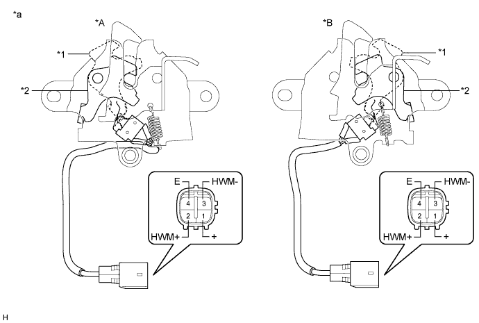
Measure the resistance according to the value(s) in the table below.
| Tester Connection | Condition | Specified Condition |
| 1 (+) - 4 (E) | Locked | 10 kΩ or higher |
| 1 (+) - 4 (E) | Unlocked | Below 1 Ω |
| 2 (HWM+) - 3 (HWM-) | Always | Below 1 Ω |
| *A | for LHD | *B | for RHD |
| *1 | Unlocked | *2 | Locked |
| *a | Component without harness connected (Security Courtesy Switch (Hood Lock Assembly)) | - | - |
|
| ||||
| OK | ||
| ||
| ||


