THEFT DETERRENT SYSTEM > Horn Circuit |
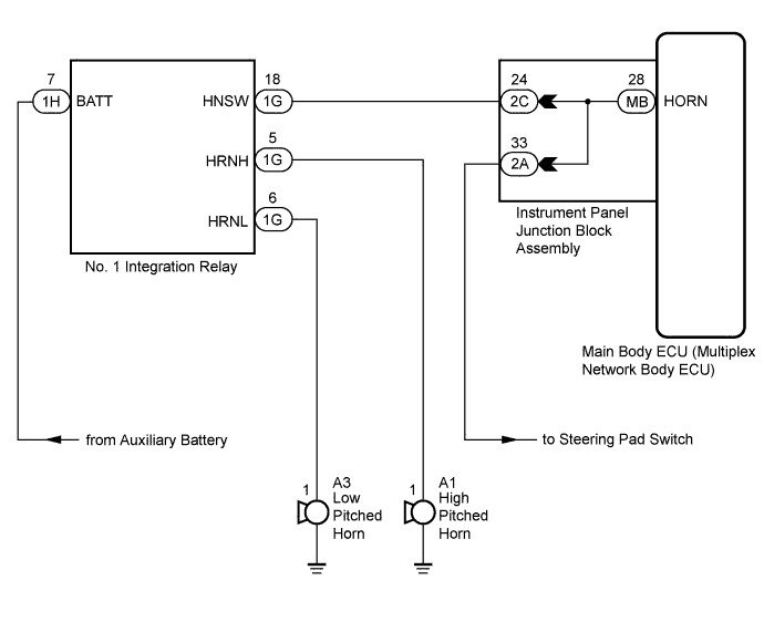
| 1.INSPECT HORNS |
Press the horn switch and check if the horns sound.
| Result | Proceed to |
| Horns sound | A |
| Horns do not sound | B |
|
| ||||
| A | |
 |
| 2.PERFORM ACTIVE TEST USING INTELLIGENT TESTER |
Connect the intelligent tester to the DLC3.
Turn the power switch on (IG).
Turn the intelligent tester on.
Enter the following menus: Body / Main Body / Active Test.
Perform the Active Test according to the display on the intelligent tester.
| Tester Display | Test Part | Control Range | Diagnostic Note |
| Vehicle Horn | Vehicle horns | ON / OFF | - |
| Result | Proceed to |
| The vehicle horns do not sound when operated through the intelligent tester | A |
| The vehicle horns sound and stop correctly when operated through the intelligent tester | B |
|
| ||||
| A | |
|
| 3.INSPECT INSTRUMENT PANEL JUNCTION BLOCK ASSEMBLY |
Disconnect the 2C instrument panel junction block assembly and MB main body ECU (multiplex network body ECU) connectors.

Measure the resistance according to the value(s) in the table below.
| Tester Connection | Condition | Specified Condition |
| 2C-24 - MB-28 (HORN) | Always | Below 1 Ω |
| 2C-24 - Body ground | Always | 10 kΩ or higher |
| *a | Component without harness connected (Instrument Panel Junction Block Assembly) | - | - |
|
| ||||
| OK | ||
 | ||
| ||

