MICROPHONE > INSTALLATION |
| 1. INSTALL AMPLIFIER MICROPHONE ASSEMBLY |
Engage the 2 claws and install the amplifier microphone assembly to map knob guide.
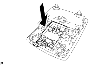 |
Install the map knob guide as shown in the illustration.
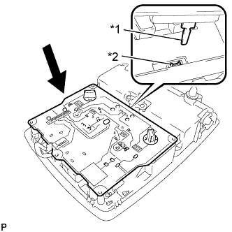 |
Install the board so that the switch lever securely engages with the hole of the switch knob as shown in the illustration.
| *1 | Switch lever |
| *2 | Switch knob |
Install the cover with the 7 screws.
Engage the guide and connect the connector.
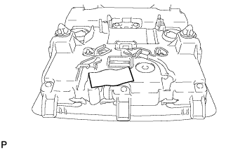 |
Put the tape back to the positions shown in the illustration in order to secure the cord to the map light assembly.
| 2. CONNECT THEFT WARNING RADAR SENSOR (w/ Intrusion Sensor) |
w/o Sliding Roof:
Engage the 2 clamps.
Install the 2 screws and connect the connector.
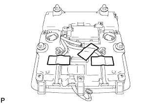 |
Put the tape back to the positions shown in the illustration in order to secure the cord to the map light assembly.
w/ Sliding Roof:
Engage the 6 clamps.
Install the 2 screws and connect the connector.
| 3. INSTALL MAP LIGHT ASSEMBLY |
Connect the connector.
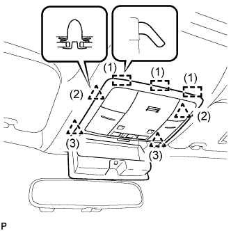 |
Engage the 3 guides and 4 clips to install the map light assembly as shown in the illustration.
Close the overhead console.
