WATER PUMP WITH MOTOR > INSTALLATION |
| 1. INSTALL INVERTER WATER PUMP ASSEMBLY |
Install the inverter water pump assembly and water pump bracket with the 3 bolts.
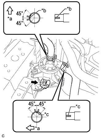 |
Connect the 2 water hose and connector.
| *a | Front Side |
| *b | Matchmark (Green) |
| *c | Matchmark (White) |
| 2. INSTALL INVERTER TRAY BRACKET |
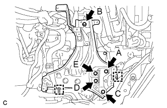 |
Position the inverter tray bracket as shown in the illustration.
Temporarily install bolt B to the inverter tray bracket.
Tighten the 5 bolts to the inverter tray bracket in the order bolt A, bolt C, bolt D, bolt E and bolt B.
Connect the 2 clamps to the inverter tray bracket.
| 3. INSTALL INVERTER RESERVE TANK ASSEMBLY |
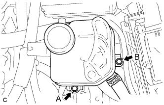 |
Temporarily install bolt A to the inverter reserve tank assembly.
Tighten the 2 bolts to the inverter reserve tank assembly in the order bolt B and bolt A.
| 4. INSTALL INVERTER WITH CONVERTER ASSEMBLY |
| 5. ADD COOLANT (for Inverter) |
| DTC No. | Detection Item |
| P0A01-726 | Motor Electronics Coolant Temperature Sensor Circuit Range / Performance |
| P0A04-725 | Motor Electronics Coolant Temperature Sensor Circuit Intermittent |
| P0A08-264 | DC / DC Converter Status Circuit |
| P0A78-284 | Drive Motor "A" Inverter Performance |
| P0A78-286 | Drive Motor "A" Inverter Performance |
| P0A7A-322 | Generator Inverter Performance |
| P0A7A-324 | Generator Inverter Performance |
| P0A93-346 | Inverter Cooling System Performance |
| P0A94-553 | DC / DC Converter Performance |
| P0A94-557 | DC / DC Converter Performance |
| P0AEE-277 | Motor Inverter Temperature Sensor "A" Circuit Range / Performance |
| P0AF1-276 | Drive Motor Inverter Temperature Sensor "A" Circuit Intermittent / Erratic |
| P0BCD-315 | Generator Inverter Temperature Sensor Circuit Range / Performance |
| P0BD0-314 | Generator Inverter Temperature Sensor Circuit Intermittent / Erratic |
| P0C39-626 | DC / DC Converter Temperature Sensor "A" Range / Performance |
| P0C3C-625 | DC / DC Converter Temperature Sensor "A" Intermittent / Erratic |
| P0C3E-628 | DC / DC Converter Temperature Sensor "B" Range / Performance |
| P0C41-627 | DC / DC Converter Temperature Sensor "B" Intermittent / Erratic |
| P0C73-776 | Motor Electronics Coolant Pump "A" Control Performance |
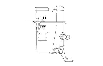 |
Slowly pour coolant into the reserve tank until it reaches the full line.
When using the intelligent tester:
Connect the intelligent tester to the DLC3.
Turn the power switch on (IG).
Enter the following menus: Powertrain / Hybrid Control / Active Test / Activate the Water Pump.
Keep the coolant at the full line in the reserve tank to compensate for the drop in coolant level when the air bleeds.
When not using the intelligent tester:
Turn the power switch on (READY). [*1]
Turn the power switch off and add coolant to the full line because the coolant level drops as the air bleeds. [*2]
Repeat steps [*1] and [*2] until air bleeding from the cooling system is completed.
After the air is completely bled from the cooling system, tighten the reserve tank cap.
|
Add coolant to the full line of the reserve tank.
| 6. INSPECT FOR COOLANT LEAK (for Inverter) |
Remove the reserve tank cap.
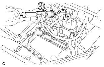 |
Install a radiator cap tester.
Pump the radiator cap tester to 122 kPa (1.2 kgf/ cm2, 18 psi), and then check that the pressure does not drop.
Reinstall the reserve tank cap.
| 7. INSTALL NO. 1 ENGINE UNDER COVER |
