HV BATTERY > INSTALLATION |
| 1. INSTALL NO. 2 HYBRID BATTERY PACK WIRE |
Connect the 2 clamps and No. 2 hybrid battery pack wire.
| 2. INSTALL NO. 1 HYBRID BATTERY PACKING |
Install the No. 1 hybrid battery packing with the 2 clamps.
| 3. INSTALL UPPER HYBRID BATTERY COVER SUB-ASSEMBLY |
Install the upper hybrid battery cover sub-assembly and No. 1 hybrid battery shield sub-assembly with the 3 bolts and 8 nuts.
| 4. INSTALL NO. 1 HYBRID BATTERY COVER INTAKE DUCT |
Install the No. 1 hybrid battery cover intake duct with the 2 clips.
| 5. INSTALL NO. 4 HYBRID VEHICLE BATTERY CARRIER BRACKET SUB-ASSEMBLY |
Install the HV battery thermistor to the No. 4 hybrid vehicle battery carrier bracket sub-assembly.
Install the No. 4 hybrid vehicle battery carrier bracket sub-assembly with the 3 bolts.
Connect the 3 wire harness clamps.
| 6. INSTALL NO. 1 HYBRID VEHICLE BATTERY CARRIER BRACKET SUB-ASSEMBLY |
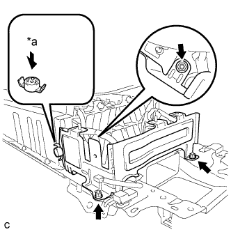 |
Install the No. 1 hybrid vehicle battery carrier bracket sub-assembly with the 3 nuts.
| *a | Push |
Install the battery cover lock striker, then push the button to lock it.
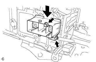 |
Install the electric vehicle battery plug assembly with the bolt as shown in the illustration.
Connect the connector.
| 7. INSTALL BATTERY SMART UNIT |
Install the battery smart unit with the 2 bolts.
Connect the 3 connectors.
| 8. INSTALL HV BATTERY |
Install the HV battery to the vehicle with the 4 bolts.
Connect the connector and electrical key oscillator clamp.
Install a new No. 3 hybrid vehicle battery carrier sheet.
Install a new No. 2 hybrid vehicle battery carrier sheet.
Install the hybrid vehicle battery lower cover plate.
| 9. INSTALL REAR CENTER SEAT BACK HINGE SUB-ASSEMBLY |
Install the rear center seat back hinge sub-assembly with the 2 bolts.
| 10. INSTALL CHILD RESTRAINT SEAT ANCHOR BRACKET SUB-ASSEMBLY LH |
Install the child restraint seat anchor bracket subassembly LH with the 2 bolts.
| 11. INSTALL CHILD RESTRAINT SEAT ANCHOR BRACKET SUB-ASSEMBLY RH |
Connect the wire harness protector clamp.
Install the child restraint seat anchor bracket subassembly RH with the 2 bolts.
| 12. INSTALL NO. 7 HYBRID VEHICLE BATTERY UPPER CARRIER BRACKET |
Install the No. 7 hybrid battery upper carrier bracket with the bolt.
Connect the 2 wire harness clamps.
| 13. INSTALL HYBRID BATTERY JUNCTION BLOCK ASSEMBLY |
Install the hybrid battery junction block assembly with the 3 nuts.
Connect the 2 connectors to the hybrid battery junction block assembly.
Connect the 2 connectors to the hybrid battery junction block assembly.
| 14. INSTALL FRAME WIRE |
Install the frame wire on the hybrid battery junction block with the 2 nuts.
Connect the clamp and frame wire.
| 15. CHECK HIGH VOLTAGE CABLE CONNECTION CONDITION |
Check that each wire harness is being installed securely.
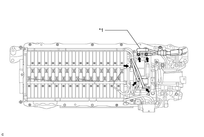
| *1 | Frame Wire | - | - |
| 16. INSTALL UPPER HYBRID BATTERY COVER SUB-ASSEMBLY |
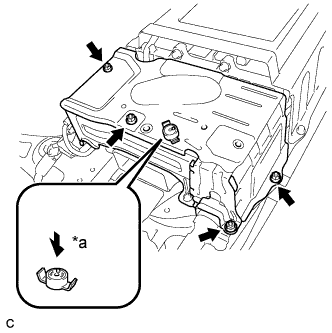 |
Install the upper hybrid battery cover sub-assembly with the 4 nuts.
| *a | Push |
Install the battery cover lock striker, then push the button to lock.
| 17. INSTALL BATTERY COOLING BLOWER ASSEMBLY |
Install the battery cooling blower assembly with the 2 bolts and nut.
Connect the battery cooling blower assembly connector and clamp.
Connect the 2 wire harness clamps.
| 18. INSTALL NO. 1 HYBRID BATTERY EXHAUST DUCT |
Insert the No. 1 hybrid battery exhaust duct with the clip.
| 19. INSTALL NO. 1 HYBRID BATTERY INTAKE DUCT |
Install the No. 1 hybrid battery intake duct with the 2 clips.
| 20. INSTALL REAR FLOOR BOARD SPACER |
Install the rear floor board spacer with the 2 clips.
| 21. INSTALL HYBRID BATTERY COVER SHEET |
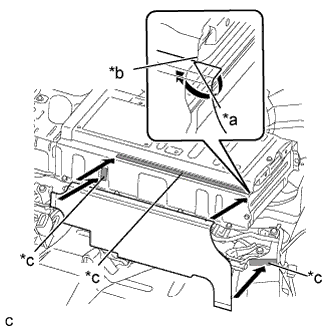 |
Align the cutout of a new hybrid battery cover sheet with the edge of the upper hybrid battery cover subassembly, and then install the hybrid battery cover sheet with the double-sided tape.
| *a | Cutout |
| *b | Edge |
| *c | Installation position |
| 22. INSTALL HYBRID VEHICLE BATTERY SHIELD SHEET |
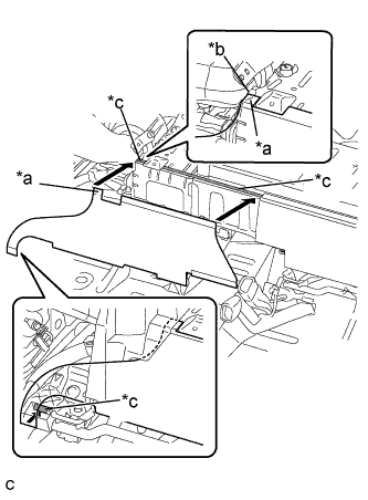 |
Align the edge of the tab of a new hybrid vehicle battery shield sheet with the edge of the hybrid battery cover sub-assembly, and then install the hybrid vehicle battery shield sheet with the double-sided tape.
| *a | Tab |
| *b | Edge |
| *c | Installation position |
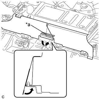 |
Overlap the hybrid vehicle battery shield sheet with the hybrid battery cover sheet, fold the edge as shown in the illustration, and secure it with the double-sided tape.
| *a | Installation position |
| 23. INSTALL REAR SEAT SIDE GARNISH RH |
| 24. INSTALL REAR SEAT SIDE GARNISH LH |
Engage the 6 claws.
Install the rear seat side garnish LH with the clip.
| 25. INSTALL REAR DOOR SCUFF PLATE RH |
| 26. INSTALL REAR DOOR SCUFF PLATE LH |
Engage the 4 claws, 2 guides and 2 clips to install the rear door scuff plate LH.
| 27. INSTALL REAR SEAT ASSEMBLY |
| 28. INSTALL REAR NO. 1 FLOOR BOARD |
Engage the 2 claws and 2 clips.
Install the rear No. 1 floor board with the bolt.
| 29. INSTALL REAR NO. 2 FLOOR BOARD SUB-ASSEMBLY |
Engage the claw and 2 clips to install the rear No. 2 floor board sub-assembly.
| 30. INSTALL REAR NO. 1 FLOOR BOARD SUB-ASSEMBLY |
Engage the 2 claws and 2 clips to install the rear No. 1 floor board sub-assembly.
| 31. INSTALL DECK FLOOR BOX LH (w/o Woofer) |
Engage the 6 guides.
Install the deck floor box LH with the clip.
| 32. INSTALL REAR NO. 4 FLOOR BOARD (w/ Woofer) |
Engage the 2 clips and 3 guides to install the rear No. 4 floor board.
| 33. INSTALL REAR NO. 4 FLOOR BOARD (w/o Woofer) |
Install the rear No. 4 floor board.
| 34. INSTALL TONNEAU COVER ASSEMBLY (w/ Tonneau Cover) |
Install the tonneau cover assembly.
| 35. INSTALL SERVICE PLUG GRIP |
