LIGHTING SYSTEM > Interior Light Circuit |
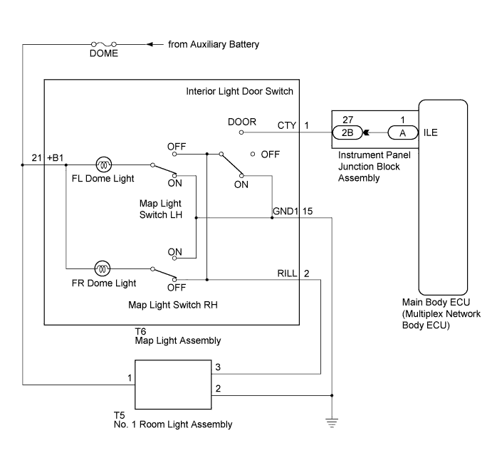
| 1.PERFORM ACTIVE TEST USING INTELLIGENT TESTER |
Connect the intelligent tester to the DLC3.
Turn the power switch on (IG).
Turn the intelligent tester on.
Enter the following menus: Body / Main Body / Active Test.
Check that the lights operate.
| Tester Display | Test Part | Control Range | Diagnostic Note |
| Illuminated Entry System | Front interior lights and rear interior light | ON/OFF | Interior light on/off switch off (not pushed), interior light door switch on (not pushed) and all doors closed |
|
| ||||
| OK | ||
 | ||
| ||
| 2.CHECK HARNESS AND CONNECTOR (AUXILIARY BATTERY - INSTRUMENT PANEL JUNCTION BLOCK ASSEMBLY) |
Disconnect the 2B instrument panel junction block assembly connector.
Measure the voltage according to the value(s) in the table below.
| Tester Connection | Condition | Specified Condition |
| 2B-27 - Body ground | Power switch off | 11 to 14 V |
|
| ||||
| OK | |
 |
| 3.INSPECT INSTRUMENT PANEL JUNCTION BLOCK ASSEMBLY |
Remove the instrument panel junction block assembly (Click here).
Remove the main body ECU (multiplex network body ECU) from the instrument panel junction block assembly.
Measure the resistance according to the value(s) in the table below.
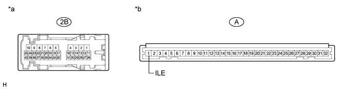
| *a | Component without harness connected (Instrument Panel Junction Block Assembly) | *b | Component without harness connected (Instrument Panel Junction Block Assembly) |
| Tester Connection | Condition | Specified Condition |
| 2B-27 - A-1 (ILE) | Always | Below 1 Ω |
| A-1 (ILE) - Body ground | Always | 10 kΩ or higher |
|
| ||||
| OK | ||
| ||
| ||


