ELECTRONIC SHIFT LEVER SYSTEM > TERMINALS OF ECU |
| TRANSMISSION CONTROL ECU INSPECTION |
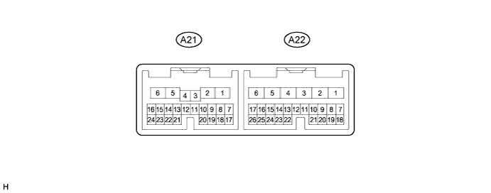
| Terminal No. (Symbol) | Wiring Color | Terminal Description | Condition | Specified Condition |
| A21-1 (MWA) - A22-6 (E01) | W - W-B | Parking lock motor | Engine stopped (hybrid system stopped), power switch on (IG) | 9 to 14 V |
| A21-2 (MVA) - A22-6 (E01) | R - W-B | Parking lock motor | Engine stopped (hybrid system stopped), power switch on (IG) | 9 to 14 V |
| A21-5 (MUA) - A22-6 (E01) | B - W-B | Parking lock motor | Engine stopped (hybrid system stopped), power switch on (IG) | 9 to 14 V |
| A21-7 (VC) - A21-19 (E2) | G - P | Power source (Rotation angle sensor) | Engine stopped (hybrid system stopped), power switch on (IG) | 4.5 to 5.5 V |
| A21-8 (RB) - A21-19 (E2) | GR - P | Rotation angle sensor signal | Power switch off → Power switch on (IG) | 0 to 1.5 V ←→ 4 to 5.5 V |
| Power switch on (IG) Changing from park (P) to neutral (N), or neutral (N) to park (P). | Pulse generation (see waveform 1) | |||
| A21-15 (BATT) - A22-1 (E1) | SB - BR | Power source (RAM) | Always | 9 to 14 V |
| A21-16 (+B) - A22-1 (E1) | GR - BR | Power source | Engine stopped (hybrid system stopped), power switch on (IG) | 9 to 14 V |
| A21-17 (RA) - A21-19 (E2) | LG - P | Rotation angle sensor signal | Power switch off → Power switch on (IG) | 0 to 1.5 V ←→ 4 to 5.5 V |
| Power switch on (IG) Changing from park (P) to neutral (N), or neutral (N) to park (P). | Pulse generation (see waveform 1) | |||
| A21-19 (E2) - Body ground | P - Body ground | Rotation angle sensor ground | Always | Below 1 Ω |
| A21-20 (IND) - A22-1 (E1) | R - BR | P position switch indicator light | Park (P) not selected → Park (P) selected [P position switch (transmission shift main switch) pushed to select park (P)] | 9 to 14 V → 0 to 1.5 V |
| A21-23 (BMA) - A22-1 (E1) | B - BR | P CON MTR relay (transaxle parking lock control relay) | Engine stopped (hybrid system stopped), power switch on (IG) | 9 to 14 V |
| A22-1 (E1) - Body ground | BR - Body ground | Ground | Always | Below 1 Ω |
| A22-5 (E02) - Body ground | W-B - Body ground | Ground | Always | Below 1 Ω |
| A22-6 (E01) - Body ground | W-B - Body ground | Ground | Always | Below 1 Ω |
| A22-15 (CA1L) - A22-1 (E1) | BR - BR | CAN communication | Power switch on (IG) | Pulse generation (see waveform 2) |
| A22-16 (CA1H) - A22-1 (E1) | Y - BR | CAN communication | Power switch on (IG) | Pulse generation (see waveform 2) |
| A22-22 (PCON) - A22-1 (E1) | LG - BR | Communication bus | Engine stopped (hybrid system stopped), power switch on (IG) | Pulse generation (see waveform 3) |
| A22-23 (PPOS) - A22-1 (E1) | V - BR | Communication bus | Engine stopped (hybrid system stopped), power switch on (IG) | Pulse generation (see waveform 3) |
| A22-24 (LIN) | B | LIN communication | - | - |
| Oscilloscope waveforms |
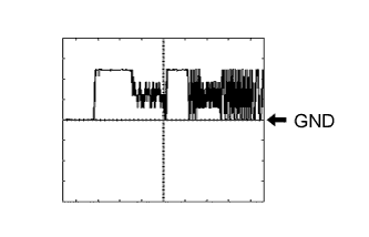 |
Waveform 1 (Rotation angle sensor signal)
| Item | Contents |
| Terminal | A21-17 (RA) - A21-19 (E2) A21-8 (RB) - A21-19 (E2) |
| Equipment setting | 2 V/DIV., 100 msec./DIV. |
| Condition | Power switch on (IG) Changing from park (P) to neutral (N), or neutral (N) to park (P). |
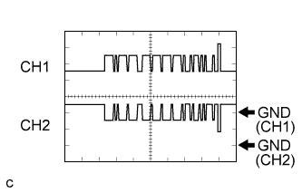 |
Waveform 2 (CAN communication signal)
| Item | Contents |
| Terminal | CH1: A22-16 (CA1H) - A22-1 (E1) CH2: A22-15 (CA1L) - A22-1 (E1) |
| Equipment setting | 1 V/DIV., 50 μs/DIV. |
| Condition | Power switch on (IG) |
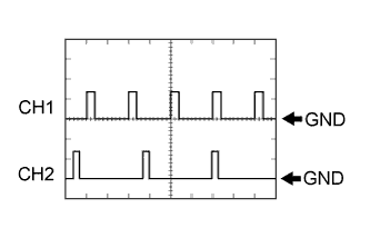 |
Waveform 3 (Transmission control communication signal)
| Item | Contents |
| Terminal | CH1: A22-22 (PCON) - A22-1 (E1) CH2: A22-23 (PPOS) - A22-1 (E1) |
| Equipment setting | 10 V/DIV., 10 ms/DIV. |
| Condition | Power switch on (IG) |
