DTC    C2301    Shift Changing Time Malfunction

for Preparation Click here


DESCRIPTION

The transmission control ECU assembly receives a P position switch signal from the power management control ECU (HV CPU) and then activates the shift control actuator assembly. At the same time, the transmission control ECU assembly detects the length of time it takes for the parking lock mechanism to switch. The transmission control ECU assembly stores this DTC when this length of time is longer than specified.

DTC No.
DTC Detection Condition
Trouble Area
C2301
A shift control actuator assembly (parking lock motor) internal malfunction (parking lock motor spins freely) is detected for 2 seconds or more.
  1. Auxiliary battery
  2. Shift control actuator assembly
  3. Hybrid vehicle transaxle assembly
  4. Transmission control ECU assembly

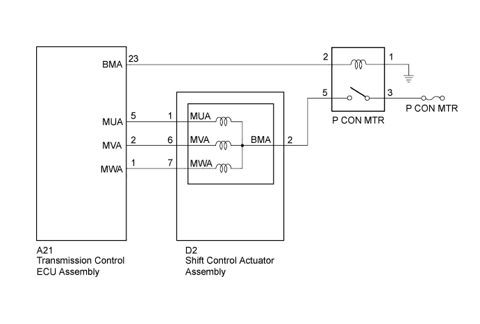
WIRING DIAGRAM


C225845E06


INSPECTION PROCEDURE

NOTICE:
  1. It may not be possible to clear the following DTCs using the intelligent tester: DTC C2300 (Actuator System Malfunction), C2301 (Shift Changing Time Malfunction), C2303 (Short in Power Source Relay Circuit), C2304 (Open or Short Circuit in U Phase), C2305 (Open or Short Circuit in V Phase), C2306 (Open or Short Circuit in W Phase), C2307 (Power Supply) and C2309 (Open in B+ Circuit). In such cases, disconnect the P CON MAIN fuse and wait for at least 60 seconds to clear the DTCs after the repair.
  2. After turning the power switch off, waiting time may be required before disconnecting the cable from the negative (-) auxiliary battery terminal. Therefore, make sure to read the disconnecting the cable from the negative (-) auxiliary battery terminal notices before proceeding with work (Click here).

1.CHECK FREEZE FRAME DATA
  1. Connect the intelligent tester to the DLC3.

  1. Turn the power switch on (IG).

  1. Enter the following menus: Chassis / Transmission Control / DTC.

  1. Read the freeze frame data of C2301.

    Result:
    Result
    Proceed to
    IG (+B) voltage is 9 V or more
    A
    IG (+B) voltage is less than 9 V
    B

  1. Turn the power switch off.


B
REPLACE AUXILIARY BATTERY (Click here)
A


2.CLEAR DTC
  1. Turn the power switch on (IG).

  1. Enter the following menus: Chassis / Transmission Control / DTC.

  1. Read and record the DTCs and freeze frame data.

  1. Turn the power switch off.

  1. Disconnect the P CON MAIN fuse and wait for at least 60 seconds.

  1. Check for DTCs again to see if the DTCs are cleared.


NEXT


3.CHARGE AUXILIARY BATTERY
  1. Charge the auxiliary battery.


NEXT


4.CHECK DTC OUTPUT (SIMULATION TEST)
  1. Connect the intelligent tester to the DLC3.

  1. Release the brake pedal and turn the power switch on (IG).

    HINT:
    Do not turn the power switch on (READY).

  1. Depress the brake pedal and move the shift lever to select neutral (N).

  1. Enter the following menus: Chassis / Transmission Control / DTC.

  1. Check if DTCs are output.

    Result:
    Result
    Proceed to
    C2301 is output
    A
    DTC is not output.
    B

  1. Turn the power switch off.


B
END (AUXILIARY BATTERY WAS INSUFFICIENTLY CHARGED)
A


5.CHECK SHIFT CONTROL ACTUATOR ASSEMBLY
  1. Disconnect the connector from the shift control actuator assembly.

  1. Remove the 3 shift control actuator bolts (Click here).

  1. Slightly pull the shift control actuator assembly from the hybrid vehicle transaxle.
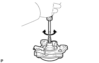


    C234956
  1. Using a screwdriver with its tip wrapped with protective tape or a piece of cloth, rotate the shaft.

    OK:
    The shift control actuator assembly turns smoothly.

    NOTICE:
    1. During this inspection, make sure to use a screwdriver with its tip wrapped with protective tape or a piece of cloth to prevent the splines of the actuator from being damaged.
    2. The shift control actuator assembly cannot be disassembled.


NG
REPLACE SHIFT CONTROL ACTUATOR ASSEMBLY (Click here)
OK


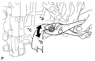
6.CHECK HYBRID VEHICLE TRANSAXLE ASSEMBLY


    C211914E02
  1. Wrap the shaft with a piece of cloth and turn it using pliers.

    OK:
    The shaft rotates smoothly in the lock and unlock directions.

    NOTICE:
    1. Rotate the shaft using torque between 4.0 to 7.0 N*m (41 to 71 kgf*cm, 36 to 61 in.*lbf).
    2. During this inspection, make sure to use a piece of cloth to prevent the shaft splines from being damaged.

    Text in Illustration 
    *a
    Lock
    *b
    Unlock
    *c
    Rotate approximately 20°

  1. Set the shaft in the lock position after the inspection.


NG
REPLACE HYBRID VEHICLE TRANSAXLE ASSEMBLY (Click here)
OK

REPLACE TRANSMISSION CONTROL ECU ASSEMBLY (Click here)