DTC C2304 Open or Short Circuit in U Phase |
DTC C2305 Open or Short Circuit in V Phase |
DTC C2306 Open or Short Circuit in W Phase |
| DTC No. | DTC Detection Condition | Trouble Area |
| C2304 | With the power switch on (IG) (auxiliary battery voltage is 8 V or more), voltage of transmission control ECU assembly terminal MUA is 6 V or less for 1 second or more. |
|
| C2305 | With the power switch on (IG) (auxiliary battery voltage is 8 V or more), voltage of transmission control ECU assembly terminal MVA is 6 V or less for 1 second or more. | |
| C2306 | With the power switch on (IG) (auxiliary battery voltage is 8 V or more), voltage of transmission control ECU assembly terminal MWA is 6 V or less for 1 second or more. |
| 1.CHECK DTC OUTPUT (TRANSMISSION CONTROL) |
Connect the intelligent tester to the DLC3.
Turn the power switch on (IG).
Enter the following menus: Chassis / Transmission Control / DTC.
Check if DTCs are output.
| Result | Proceed to |
| C2304, C2305 and C2306 are detected simultaneously | A |
| One of C2304, C2305 and C2306 is detected | B |
Turn the power switch off.
|
| ||||
| A | |
 |
| 2.CHECK FREEZE FRAME DATA |
Connect the intelligent tester to the DLC3.
Turn the power switch on (IG).
Enter the following menus: Chassis / Transmission Control / DTC.
Read the freeze frame data of C2304, 2305 and 2306.
| Result | Proceed to |
| IG (+B) voltage is 9 V or more | A |
| IG (+B) voltage is less than 9 V | B |
Turn the power switch off.
|
| ||||
| A | |
|
| 3.CLEAR DTC |
Turn the power switch on (IG).
Enter the following menus: Chassis / Transmission Control / DTC.
Read and record the DTCs and freeze frame data.
Turn the power switch off.
Disconnect the P CON MAIN fuse and wait for at least 60 seconds.
Check for DTCs again to see if the DTCs are cleared.
| NEXT | |
|
| 4.CHARGE AUXILIARY BATTERY |
Charge the auxiliary battery.
| NEXT | |
|
| 5.CHECK DTC OUTPUT (SIMULATION TEST) |
Connect the intelligent tester to the DLC3.
Release the brake pedal and turn the power switch on (IG).
Depress the brake pedal and move the shift lever to select neutral (N).
Enter the following menus: Chassis / Transmission Control / DTC.
Check if DTCs are output.
| Result | Proceed to |
| C2304, 2305 or 2306 is output | A |
| DTC is not output. | B |
Turn the power switch off.
|
| ||||
| A | |
|
| 6.READ VALUE USING INTELLIGENT TESTER (U, V, W VOLTAGE) |
Connect the intelligent tester to the DLC3.
Turn the power switch on (IG).
Enter the following menus: Chassis / Transmission Control / Data List / U Phase Voltage Value, V Phase Voltage Value, W Phase Voltage Value.
Read the data list displayed on the intelligent tester.
| Tester Display | Switch Condition | Specified Condition |
| U Phase Voltage Value | Power switch on (IG) | 9 to 14 V |
| V Phase Voltage Value | Power switch on (IG) | 9 to 14 V |
| W Phase Voltage Value | Power switch on (IG) | 9 to 14 V |
Turn the power switch off.
|
| ||||
| OK | ||
 | ||
| ||
| 7.CHECK HARNESS AND CONNECTOR (TRANSMISSION CONTROL ECU ASSEMBLY - SHIFT CONTROL ACTUATOR) |
Disconnect connector A21 from the transmission control ECU assembly.
Disconnect connector D2 from the shift control actuator assembly.
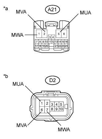 |
Measure the resistance according to the value(s) in the table below.
| Tester Connection | Switch Condition | Specified Condition |
| A21-5 (MUA) - D2-1 (MUA) | Power switch off | Below 1 Ω |
| A21-2 (MVA) - D2-6 (MVA) | Power switch off | Below 1 Ω |
| A21-1 (MWA) - D2-7 (MWA) | Power switch off | Below 1 Ω |
| Tester Connection | Switch Condition | Specified Condition |
| A21-5 (MUA) or D2-1 (MUA) - Body ground and other terminals | Power switch off | 10 kΩ or higher |
| A21-2 (MVA) or D2-6 (MVA) - Body ground and other terminals | Power switch off | 10 kΩ or higher |
| A21-1 (MWA) or D2-7 (MWA) - Body ground and other terminals | Power switch off | 10 kΩ or higher |
| *a | Front view of wire harness connector (to Transmission Control ECU Assembly) |
| *b | Front view of wire harness connector (to Shift Control Actuator Assembly) |
Connect the shift control actuator assembly connector.
Connect the transmission control ECU assembly connector.
|
| ||||
| OK | |
|
| 8.CHECK HARNESS AND CONNECTOR (SHIFT CONTROL ACTUATOR ASSEMBLY - P CON MTR RELAY) |
Disconnect connector D2 from the shift control actuator assembly.
Remove the P CON MTR relay (transaxle parking lock control relay) from the engine room junction block assembly.
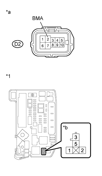 |
Measure the resistance according to the value(s) in the table below.
| Tester Connection | Switch Condition | Specified Condition |
| D2-2 (BMA) - 5 (P CON MTR relay) | Power switch off | Below 1 Ω |
| Tester Connection | Switch Condition | Specified Condition |
| D2-2 (BMA) or 5 (P CON MTR relay) - Body ground and other terminals | Power switch off | 10 kΩ or higher |
| *1 | Engine Room Junction Block Assembly |
| *a | Front view of wire harness connector (to Shift Control Actuator Assembly) |
| *b | P CON MTR Relay (transaxle parking lock control relay) Connector of Engine Room Junction Block Assembly |
Reinstall the P CON MTR relay (transaxle parking lock control relay).
Connect the shift control actuator assembly connector.
|
| ||||
| OK | |
|
| 9.CHECK SHIFT CONTROL ACTUATOR ASSEMBLY |
Disconnect connector A21 from the transmission control ECU assembly connector.
Remove the P CON MTR relay (transaxle parking lock control relay) from the engine room junction block assembly.
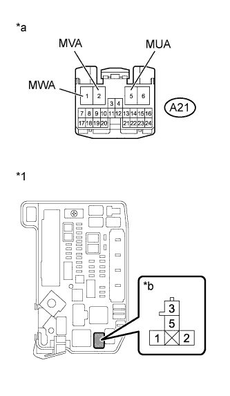 |
Measure the resistance according to the value(s) in the table below.
| Tester Connection | Switch Condition | Specified Condition |
| A21-5 (MUA) - 5 (P CON MTR relay) | Power switch off | Below 50 Ω |
| A21-2 (MVA) - 5 (P CON MTR relay) | Power switch off | Below 50 Ω |
| A21-1 (MWA) - 5 (P CON MTR relay) | Power switch off | Below 50 Ω |
| Tester Connection | Switch Condition | Specified Condition |
| A21-5 (MUA) - Body ground | Power switch off | 10 kΩ or higher |
| A21-2 (MVA) - Body ground | Power switch off | 10 kΩ or higher |
| A21-1 (MWA) - Body ground | Power switch off | 10 kΩ or higher |
| 5 (P CON MTR relay) - Body ground | Power switch off | 10 kΩ or higher |
| *1 | Engine Room Junction Block Assembly |
| *a | Front view of wire harness connector (to Transmission Control ECU Assembly) |
| *b | P CON MTR Relay (transaxle parking lock control relay) Connector of Engine Room Junction Block Assembly |
Reinstall the P CON MTR relay (transaxle parking lock control relay).
Connect the transmission control ECU assembly connector.
|
| ||||
| OK | |
|
| 10.INSPECT P CON MTR RELAY (TRANSAXLE PARKING LOCK CONTROL RELAY) |
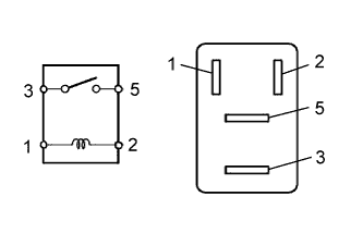 |
Remove the P CON MTR relay (transaxle parking lock control relay) from the engine room junction block assembly.
Measure the resistance according to the value(s) in the table below.
| Tester Connection | Condition | Specified Condition |
| 3 - 5 | Auxiliary battery voltage is not applied between terminals 1 and 2 | 10 kΩ or higher |
| Auxiliary battery voltage is applied between terminals 1 and 2 | Below 1 Ω |
Reinstall the P CON MTR relay (transaxle parking lock control relay).
|
| ||||
| OK | |
|
| 11.CHECK HARNESS AND CONNECTOR (TRANSMISSION CONTROL ECU ASSEMBLY - P CON MTR RELAY) |
Disconnect connector A21 from the transmission control ECU assembly.
Remove the P CON MTR relay (transaxle parking lock control relay) from the engine room junction block assembly.
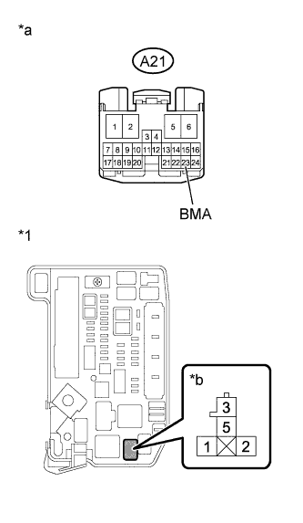 |
Measure the resistance according to the value(s) in the table below.
| Tester Connection | Switch Condition | Specified Condition |
| A21-23 (BMA) - 2 (P CON MTR relay) | Power switch off | Below 1 Ω |
| Tester Connection | Switch Condition | Specified Condition |
| A21-23 (BMA) or 2 (P CON MTR relay) - Body ground and other terminals | Power switch off | 10 kΩ or higher |
| *1 | Engine Room Junction Block Assembly |
| *a | Front view of wire harness connector (to Transmission Control ECU Assembly) |
| *b | P CON MTR Relay (transaxle parking lock control relay) Connector of Engine Room Junction Block Assembly |
Reinstall the P CON MTR relay (transaxle parking lock control relay).
Connect the transmission control ECU assembly connector.
|
| ||||
| OK | |
|
| 12.CHECK HARNESS AND CONNECTOR (P CON MTR RELAY - BODY GROUND) |
Remove the P CON MTR relay (transaxle parking lock control relay) from the engine room junction block assembly.
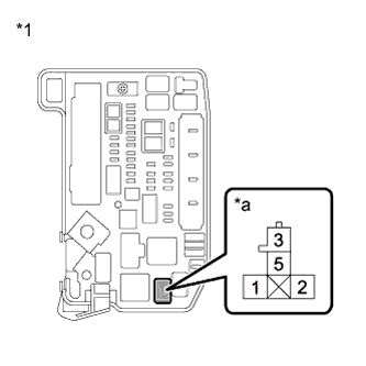 |
Measure the resistance according to the value(s) in the table below.
| Tester Connection | Switch Condition | Specified Condition |
| 1 (P CON MTR relay) - Body ground | Power switch off | Below 1 Ω |
| *1 | Engine Room Junction Block Assembly |
| *a | P CON MTR Relay (transaxle parking lock control relay) Connector of Engine Room Junction Block Assembly |
Reinstall the P CON MTR relay (transaxle parking lock control relay).
|
| ||||
| OK | |
|
| 13.CHECK HARNESS AND CONNECTOR (P CON MTR RELAY POWER SOURCE CIRCUIT) |
Remove the P CON MTR relay (transaxle parking lock control relay) from the engine room junction block assembly.
|
Measure the voltage according to the value(s) in the table below.
| Tester Connection | Condition | Specified Condition |
| 3 (P CON MTR relay) - Body ground | Always | 9 to 14 V |
| *1 | Engine Room Junction Block Assembly |
| *a | P CON MTR Relay (transaxle parking lock control relay) Connector of Engine Room Junction Block Assembly |
Reinstall the P CON MTR relay (transaxle parking lock control relay).
|
| ||||
| OK | ||
| ||
| ||


