DTC C2307 Power Supply |
| DTC No. | DTC Detection Condition | Trouble Area |
| C2307 | With the power switch on (IG) (IG circuit malfunction is not detected), current of the parking lock motor is 50 A or more or there is an open in the transmission control ECU assembly terminal E1 circuit for 0.1 seconds or more. |
|
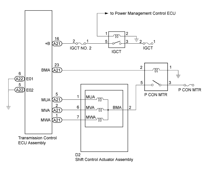
| 1.CHECK HARNESS AND CONNECTOR (TRANSMISSION CONTROL ECU ASSEMBLY - BODY GROUND) |
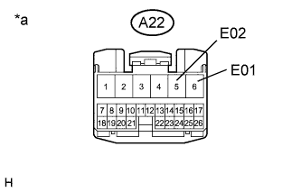
Disconnect connector A22 from the transmission control ECU assembly.
 |
Measure the resistance according to the value(s) in the table below.
| Tester Connection | Switch Condition | Specified Condition |
| A22-6 (E01) - Body ground | Power switch off | Below 1 Ω |
| A22-5 (E02) - Body ground | Power switch off | Below 1 Ω |
| *a | Front view of wire harness connector (to Transmission Control ECU Assembly) |
Connect the transmission control ECU assembly connector.
|
| ||||
| OK | |
 |
| 2.CHECK HARNESS AND CONNECTOR (TRANSMISSION CONTROL ECU ASSEMBLY - SHIFT CONTROL ACTUATOR) |
Disconnect connector A21 from the transmission control ECU assembly.
Disconnect connector D2 from the shift control actuator assembly.
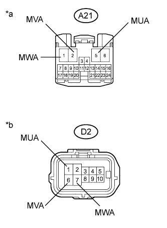 |
Measure the resistance according to the value(s) in the table below.
| Tester Connection | Switch Condition | Specified Condition |
| A21-5 (MUA) or D2-1 (MUA) - Body ground and other terminals | Power switch off | 10 kΩ or higher |
| A21-2 (MVA) or D2-6 (MVA) - Body ground and other terminals | Power switch off | 10 kΩ or higher |
| A21-1 (MWA) or D2-7 (MWA) - Body ground and other terminals | Power switch off | 10 kΩ or higher |
| *a | Front view of wire harness connector (to Transmission Control ECU Assembly) |
| *b | Front view of wire harness connector (to Shift Control Actuator Assembly) |
Connect the shift control actuator assembly connector.
Connect the transmission control ECU assembly connector.
|
| ||||
| OK | ||
 | ||
| ||

