DTC C2311 Communication Error from HV ECU |
| DTC No. | DTC Detection Condition | Trouble Area |
| C2311 | With the power switch on (IG) (IG circuit malfunction is not detected), a signal cannot be received from the power management control ECU (open or short in the PCON terminal circuit) or a pulse signal malfunction is received from the power management control ECU for 2 seconds or more. |
|
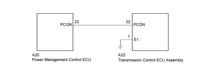
| 1.CHECK TRANSMISSION CONTROL ECU ASSEMBLY |
Turn the power switch on (IG).
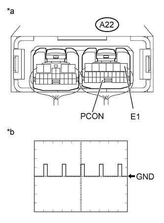 |
Connect an oscilloscope between the transmission control ECU assembly terminals specified in the table below, and measure the waveform.
| Item | Contents |
| Symbols | A22-22 (PCON) - A22-1 (E1) |
| Tool setting | 10 V/DIV., 10 msec./DIV. |
| Vehicle condition | Power switch on (IG) |
| *a | Component with harness connected (Transmission Control ECU Assembly) |
| *b | Waveform |
Turn the power switch off.
|
| ||||
| OK | ||
 | ||
| ||
| 2.CHECK HARNESS AND CONNECTOR (TRANSMISSION CONTROL ECU - POWER MANAGEMENT CONTROL ECU) |
Disconnect connector A22 from the transmission control ECU assembly.
Disconnect connector A20 from the power management control ECU.
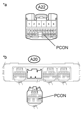 |
Measure the resistance according to the value(s) in the table below.
| Tester Connection | Switch Condition | Specified Condition |
| A22-22 (PCON) - A20-22 (PCON) | Power switch off | Below 1 Ω |
| Tester Connection | Switch Condition | Specified Condition |
| A22-22 (PCON) or A20-22 (PCON) - Body ground and other terminals | Power switch off | 10 kΩ or higher |
| *a | Front view of wire harness connector (to Transmission Control ECU Assembly) |
| *b | Rear view of wire harness connector (to Power Management Control ECU) |
Connect the power management control ECU connector.
Connect the transmission control ECU assembly connector.
|
| ||||
| OK | ||
| ||
| ||


