ELECTRONIC SHIFT LEVER SYSTEM > "P" Position Switch Indicator Light Circuit |
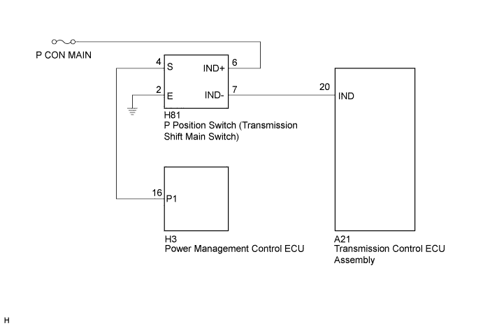
| 1.CHECK P POSITION SWITCH (INDICATOR LIGHT) |
Turn the power switch on (IG).
Depress the brake pedal and move the shift lever to select neutral (N).
Inspect the indicator light condition by operating the P position switch (transmission shift main switch).
| Condition of Indicator Light | Proceed to |
| Indicator light does not go off. (Remains on) | A |
| Indicator light does not come on. | B |
Turn the power switch off.
|
| ||||
| A | |
 |
| 2.CHECK P POSITION SWITCH (INDICATOR LIGHT) |
Disconnect connector A21 from the transmission control ECU assembly.
Turn the power switch on (IG).
Inspect the indicator light condition by operating the P position switch (transmission shift main switch).
| Condition of Indicator Light | Proceed to |
| Indicator light does not go off. (Remains on) | A |
| Indicator light goes off. | B |
Turn the power switch off.
Connect the transmission control ECU assembly connector.
|
| ||||
| A | |
|
| 3.CHECK HARNESS AND CONNECTOR (TRANSMISSION CONTROL ECU - P POSITION SWITCH) |
Disconnect connector A21 from the transmission control ECU assembly.
Disconnect connector H81 from the P position switch (transmission shift main switch).
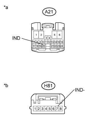 |
Measure the resistance according to the value(s) in the table below.
| Tester Connection | Switch Condition | Specified Condition |
| A21-20 (IND) or H81-7 (IND-) - Body ground and other terminals | Power switch off | 10 kΩ or higher |
| *a | Front view of wire harness connector (to Transmission Control ECU Assembly) |
| *b | Front view of wire harness connector (to P Position Switch (Transmission Shift Main Switch)) |
Connect the P position switch (transmission shift main switch) connector.
Connect the transmission control ECU assembly connector.
|
| ||||
| OK | ||
 | ||
| ||
| 4.CHECK HARNESS AND CONNECTOR (P POSITION SWITCH POWER SOURCE CIRCUIT) |
Disconnect the connector from the P position switch (transmission shift main switch).
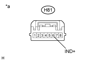 |
Measure the voltage according to the value(s) in the table below.
| Tester Connection | Switch Condition | Specified Condition |
| H81-6 (IND+) - Body ground | Power switch off | 9 to 14 V |
| *a | Front view of wire harness connector (to P Position Switch (Transmission Shift Main Switch)) |
Connect the P position switch (transmission shift main switch) connector.
|
| ||||
| OK | |
|
| 5.INSPECT P POSITION SWITCH |
Disconnect the connector from the P position switch (transmission shift main switch).
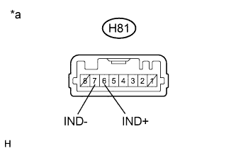 |
Apply auxiliary battery voltage between terminals H81-6 (IND+) and H81-7 (IND-) and check the indicator light.
| Condition | Specified Condition |
| Auxiliary battery voltage applied between terminals H81-6 (IND+) and H81-7 (IND-) | Comes on |
| *a | Component without harness connected (P Position Switch (Transmission Shift Main Switch)) |
Connect the P position switch (transmission shift main switch) connector.
|
| ||||
| OK | |
|
| 6.CHECK HARNESS AND CONNECTOR (TRANSMISSION CONTROL ECU - P POSITION SWITCH) |
Disconnect connector A21 from the transmission control ECU assembly.
Disconnect the connector from the P position switch (transmission shift main switch).
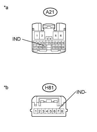 |
Measure the resistance according to the value(s) in the table below.
| Tester Connection | Switch Condition | Specified Condition |
| A21-20 (IND) - H81-7 (IND-) | Power switch off | Below 1 Ω |
| *a | Front view of wire harness connector (to Transmission Control ECU Assembly) |
| *b | Front view of wire harness connector (to P Position Switch (Transmission Shift Main Switch)) |
Connect the P position switch (transmission shift main switch) connector.
Connect the transmission control ECU assembly connector.
|
| ||||
| OK | ||
| ||
| ||


