WIPER AND WASHER SYSTEM > TERMINALS OF ECU |
| CHECK WINDSHIELD WIPER RELAY ASSEMBLY |
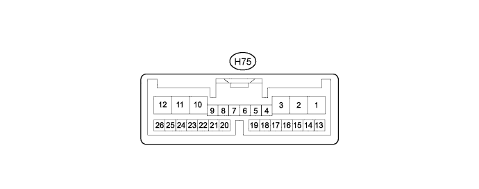
Disconnect the H75 windshield wiper relay assembly connector.
Measure the voltage and resistance according to the value(s) in the table below.
| Terminal No. (Symbol) | Wiring Color | Terminal Description | Condition | Specified Condition |
| H75-4 (W) - Body ground | B - Body ground | Front washer switch circuit | Front washer switch on | Below 1 Ω |
| Front washer switch off | 10 kΩ or higher | |||
| H75-6 (VR2) - H75-7 (VR1) | W - G | Adjusting volume circuit | Windshield wiper switch adjusting ring changed from (+) side to (-) side | 0 to 2.7 kΩ |
| H75-12 (IG) - Body ground | B - Body ground | Power source circuit | Power switch on (IG) | 11 to 14 V |
| Power switch off | Below 1 V | |||
| H75-23 (WIG) - Body ground | B - Body ground | Power source circuit | Power switch on (IG) | 11 to 14 V |
| Power switch off | Below 1 V | |||
| H75-26 (E) - Body ground | W-B - Body ground | Body ground | Always | Below 1 Ω |
Reconnect the H75 windshield wiper relay assembly connector.
Measure the voltage according to the value(s) in the table below.
| Terminal No. (Symbol) | Wiring Color | Terminal Description | Condition | Specified Condition |
| H75-1 (+2S) - Body ground | R - Body ground | Front wiper low speed signal circuit | Power switch on (IG), front wiper switch in low position | 11 to 14 V |
| Power switch on (IG), front wiper switch not in low position | Below 1 V | |||
| H75-2 (+1) - Body ground | R - Body ground | Front wiper motor low speed signal circuit | Front wiper motor in low operation | 11 to 14 V |
| Front wiper motor off | Below 1 V | |||
| H75-3 (+2) - Body ground | W - Body ground | Front wiper motor high speed signal circuit | Front wiper motor in high operation | 11 to 14 V |
| Front wiper motor off | Below 1 V | |||
| H75-4 (W) - Body ground | B - Body ground | Front washer motor circuit | Front washer switch on | Below 1 V |
| Front washer switch off | 11 to 14 V | |||
| H75-8 (SIG) - Body ground | R - Body ground | Power source circuit | Power switch on (IG) | 7.5 to 8.5 V |
| Power switch off | Below 1 V | |||
| H75-10 (+SM) - Body ground | G - Body ground | Front wiper motor operation signal | Front wiper motor in low or high operation | 11 to 14 V |
| Front wiper motor off | Below 1 V | |||
| H75-11 (+SSW) - Body ground | G - Body ground | Front wiper motor operation signal | Power switch on (IG), front wiper switch off or in AUTO, front wiper motor operates | 11 to 14 V |
| Front wiper motor off | Below 1 V | |||
| H75-14 (PA1) - Body ground | LG - Body ground | Rain sensor signal | Power switch on (IG) | Pulse generation |
| H75-17 (C1) - H75-16 (CO) | V - Y | IG signal circuit | Power switch on (IG) | 11 to 14 V |
| Power switch off | Below 1 V | |||
| H75-19 (SPD) - Body ground | V - Body ground | Speed signal | Power switch on (IG), wheel being rotated | Pulse generation |
| CHECK HEADLIGHT CLEANER CONTROL RELAY |
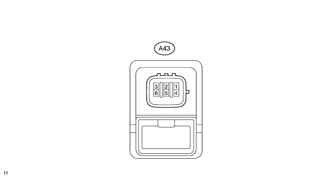
Disconnect the A43 headlight cleaner control relay connector.
Measure the voltage and resistance according to the value(s) in the table below.
| Terminal No. (Symbol) | Wiring Color | Terminal Description | Condition | Specified Condition |
| A43-1 (HDLO) - A43-4 (E) | L - W-B | Low beam headlight signal | Light control switch in head position | Below 1 V |
| Light control switch off | 11 to 14 V | |||
| A43-2 (H) - A43-4 (E) | BR - W-B | Headlight cleaner switch operation signal | Power switch on (IG) and headlight cleaner switch off | 11 to 14 V |
| Power switch on (IG), light control switch in head position and headlight cleaner switch on | Below 1 V | |||
| A43-3 (IG) - A43-4 (E) | B - W-B | Power switch on (IG) signal (Power source circuit) | Power switch off | Below 1 V |
| Power switch on (IG) | 11 to 14 V | |||
| A43-4 (E) - Body ground | W-B - Body ground | Body ground | Always | Below 1 Ω |
| A43-5 (FRWA) - A43-4 (E) | R - W-B | Front washer switch signal | Power switch on (IG) and front washer switch off | 11 to 14 V |
| Power switch on (IG) and front washer switch on | Below 1 V |
