WIPER AND WASHER SYSTEM > Wiper and Washer Switch Circuit |
| 1.INSPECT WINDSHIELD WIPER SWITCH ASSEMBLY |
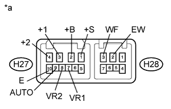 |
LHD, RHD Light Control Switch LH Side Type:
Remove the windshield wiper switch assembly (Click here).
Measure the resistance according to the value(s) in the table below.
| Tester Connection | Switch Condition | Specified Condition |
| H27-3 (+1) - H27-1 (+S) | OFF | Below 1 Ω |
| H27-3 (+1) - H27-2 (+B) | MIST | |
| LO | ||
| H27-2 (+B) - H27-4 (+2) | HI | |
| H27-9 (AUTO) - H27-10 (E) | AUTO |
| Tester Connection | Switch Condition | Specified Condition |
| H28-2 (EW) - H28-3 (WF) | ON | Below 1 Ω |
| OFF | 10 kΩ or higher |
| Tester Connection | Condition | Specified Condition |
| H27-7 (VR1) - H27-8 (VR2) | Adjusting ring changed from (+) side to (-) side | 0 to 2.7 kΩ |
| *a | Component without harness connected (to Windshield Wiper Switch Assembly) |
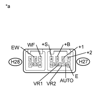 |
RHD Light Control Switch RH Side Type:
Remove the windshield wiper switch assembly (Click here).
Measure the resistance according to the value(s) in the table below.
| Tester Connection | Switch Condition | Specified Condition |
| H27-2 (+1) - H27-4 (+S) | OFF | Below 1 Ω |
| H27-2 (+1) - H27-3 (+B) | MIST | |
| LO | ||
| H27-3 (+B) - H27-1 (+2) | HI | |
| H27-6 (AUTO) - H27-5 (E) | AUTO |
| Tester Connection | Switch Condition | Specified Condition |
| H28-2 (EW) - H28-1 (WF) | ON | Below 1 Ω |
| OFF | 10 kΩ or higher |
| Tester Connection | Condition | Specified Condition |
| H27-8 (VR1) - H27-7 (VR2) | Adjusting ring changed from (+) side to (-) side | 0 to 2.7 kΩ |
| *a | Component without harness connected (to Windshield Wiper Switch Assembly) |
|
| ||||
| OK | |
 |
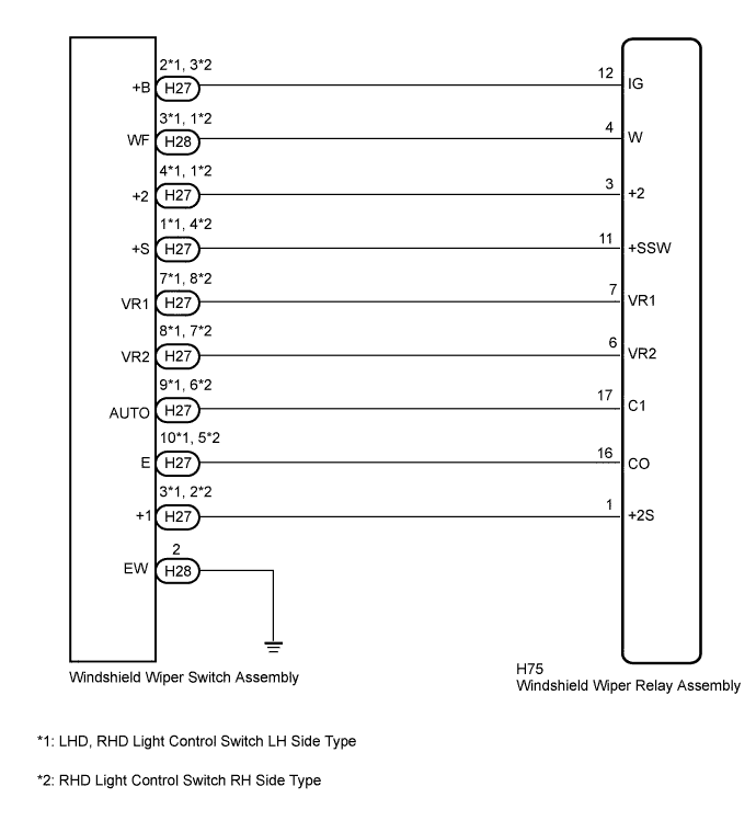
| 2.CHECK HARNESS AND CONNECTOR (WIPER SWITCH - WIPER RELAY AND BODY GROUND) |
LHD, RHD Light Control Switch LH Side Type:
Disconnect the H28 and H27 windshield wiper switch assembly connectors.
Disconnect the H75 windshield wiper relay assembly connector.
Measure the resistance according to the value(s) in the table below.
| Tester Connection | Condition | Specified Condition |
| H27-2 (+B) - H75-12 (IG) | Always | Below 1 Ω |
| H27-2 (+B) - Body ground | Always | 10 kΩ or higher |
| H27-3 (+1) - H75-1 (+2S) | Always | Below 1 Ω |
| H27-3 (+1) - Body ground | Always | 10 kΩ or higher |
| H27-4 (+2) - H75-3 (+2) | Always | Below 1 Ω |
| H27-4 (+2) - Body ground | Always | 10 kΩ or higher |
| H27-1 (+S) - H75-11 (+SSW) | Always | Below 1 Ω |
| H27-1 (+S) - Body ground | Always | 10 kΩ or higher |
| H27-9 (AUTO) - H75-17 (C1) | Always | Below 1 Ω |
| H27-9 (AUTO) - Body ground | Always | 10 kΩ or higher |
| H27-10 (E) - H75-16 (CO) | Always | Below 1 Ω |
| H27-10 (E) - Body ground | Always | 10 kΩ or higher |
| H27-7 (VR1) - H75-7 (VR1) | Always | Below 1 Ω |
| H27-7 (VR1) - Body ground | Always | 10 kΩ or higher |
| H27-8 (VR2) - H75-6 (VR2) | Always | Below 1 Ω |
| H27-8 (VR2) - Body ground | Always | 10 kΩ or higher |
| H28-3 (WF) - H75-4 (W) | Always | Below 1 Ω |
| H28-3 (WF) - Body ground | Always | 10 kΩ or higher |
| H28-2 (EW) - Body ground | Always | Below 1 Ω |
RHD Light Control Switch RH Side Type:
Disconnect the H28 and H27 windshield wiper switch assembly connectors.
Disconnect the H75 windshield wiper relay assembly connector.
Measure the resistance according to the value(s) in the table below.
| Tester Connection | Condition | Specified Condition |
| H27-3 (+B) - H75-12 (IG) | Always | Below 1 Ω |
| H27-3 (+B) - Body ground | Always | 10 kΩ or higher |
| H27-2 (+1) - H75-1 (+2S) | Always | Below 1 Ω |
| H27-2 (+1) - Body ground | Always | 10 kΩ or higher |
| H27-1 (+2) - H75-3 (+2) | Always | Below 1 Ω |
| H27-1 (+2) - Body ground | Always | 10 kΩ or higher |
| H27-4 (+S) - H75-11 (+SSW) | Always | Below 1 Ω |
| H27-4 (+S) - Body ground | Always | 10 kΩ or higher |
| H27-6 (AUTO) - H75-17 (C1) | Always | Below 1 Ω |
| H27-6 (AUTO) - Body ground | Always | 10 kΩ or higher |
| H27-5 (E) - H75-16 (CO) | Always | Below 1 Ω |
| H27-5 (E) - Body ground | Always | 10 kΩ or higher |
| H27-8 (VR1) - H75-7 (VR1) | Always | Below 1 Ω |
| H27-8 (VR1) - Body ground | Always | 10 kΩ or higher |
| H27-7 (VR2) - H75-6 (VR2) | Always | Below 1 Ω |
| H27-7 (VR2) - Body ground | Always | 10 kΩ or higher |
| H28-1 (WF) - H75-4 (W) | Always | Below 1 Ω |
| H28-1 (WF) - Body ground | Always | 10 kΩ or higher |
| H28-2 (EW) - Body ground | Always | Below 1 Ω |
|
| ||||
| OK | ||
 | ||
| ||

