WIPER AND WASHER SYSTEM > Front Wiper Motor Circuit |
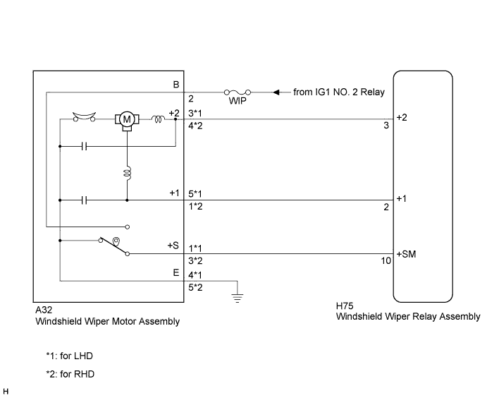
| 1.INSPECT WINDSHIELD WIPER MOTOR ASSEMBLY |
for LHD:
Remove the windshield wiper motor assembly (Click here).
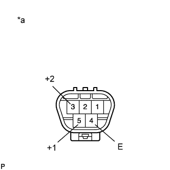 |
Check low speed operation.
Connect an auxiliary battery positive (+) lead to terminal 5 (+1) and a negative (-) lead to terminal 4 (E), and check that the motor operates at low speed.
Check high speed operation.
Connect an auxiliary battery positive (+) lead to terminal 3 (+2) and a negative (-) lead to terminal 4 (E), and check that the motor operates at high speed.
| *a | Component without harness connected (Windshield Wiper Motor Assembly) |
for RHD:
Remove the windshield wiper motor assembly (Click here).
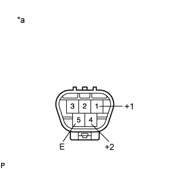 |
Check low speed operation.
Connect an auxiliary battery positive (+) lead to terminal 1 (+1) and a negative (-) lead to terminal 5 (E), and check that the motor operates at low speed.
Check high speed operation.
Connect an auxiliary battery positive (+) lead to terminal 4 (+2) and a negative (-) lead to terminal 5 (E), and check that the motor operates at high speed.
| *a | Component without harness connected (Windshield Wiper Motor Assembly) |
|
| ||||
| OK | |
 |
| 2.CHECK HARNESS AND CONNECTOR (WINDSHIELD WIPER MOTOR ASSEMBLY - BATTERY AND BODY GROUND) |
for LHD:
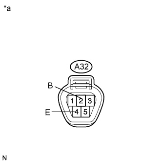 |
Disconnect the A32 windshield wiper motor connector.
Measure the voltage according to the value(s) in the table below.
| Tester Connection | Condition | Specified Condition |
| A32-2 (B) - Body ground | Power switch on (IG) | 11 to 14 V |
Measure the resistance according to the value(s) in the table below.
| Tester Connection | Condition | Specified Condition |
| A32-4 (E) - Body ground | Always | Below 1 Ω |
| *a | Front view of wire harness connector (to Windshield Wiper Motor Assembly) |
for RHD:
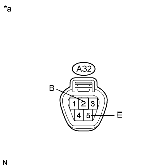 |
Disconnect the A32 windshield wiper motor connector.
Measure the voltage according to the value(s) in the table below.
| Tester Connection | Condition | Specified Condition |
| A32-2 (B) - Body ground | Power switch on (IG) | 11 to 14 V |
Measure the resistance according to the value(s) in the table below.
| Tester Connection | Condition | Specified Condition |
| A32-5 (E) - Body ground | Always | Below 1 Ω |
| *a | Front view of wire harness connector (to Windshield Wiper Motor Assembly) |
|
| ||||
| OK | |
|
| 3.CHECK HARNESS AND CONNECTOR (WINDSHIELD WIPER MOTOR - WINDSHIELD WIPER RELAY) |
for LHD:
Disconnect the H75 windshield wiper relay assembly connector.
Measure the resistance according to the value(s) in the table below.
| Tester Connection | Condition | Specified Condition |
| A32-5 (+1) - H75-2 (+1) | Always | Below 1 Ω |
| A32-5 (+1) - Body ground | Always | 10 kΩ or higher |
| A32-3 (+2) - H75-3 (+2) | Always | Below 1 Ω |
| A32-3 (+2) - Body ground | Always | 10 kΩ or higher |
| A32-1 (+S) - H75-10 (+SM) | Always | Below 1 Ω |
| A32-1 (+S) - Body ground | Always | 10 kΩ or higher |
for RHD:
Disconnect the H75 windshield wiper relay assembly connector.
Measure the resistance according to the value(s) in the table below.
| Tester Connection | Condition | Specified Condition |
| A32-1 (+1) - H75-2 (+1) | Always | Below 1 Ω |
| A32-1 (+1) - Body ground | Always | 10 kΩ or higher |
| A32-4 (+2) - H75-3 (+2) | Always | Below 1 Ω |
| A32-4 (+2) - Body ground | Always | 10 kΩ or higher |
| A32-3 (+S) - H75-10 (+SM) | Always | Below 1 Ω |
| A32-3 (+S) - Body ground | Always | 10 kΩ or higher |
|
| ||||
| OK | ||
 | ||
| ||

