REAR VIEW MONITOR SYSTEM > Reverse Signal Circuit |
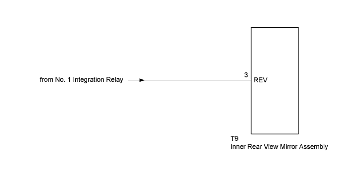
| 1.CHECK BACK-UP LIGHT ASSEMBLY |
Move the shift lever to R and check if the back-up light comes on.
|
| ||||
| OK | |
 |
| 2.INSPECT INNER REAR VIEW MIRROR ASSEMBLY (REV) |
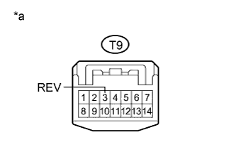 |
Disconnect the T9 connector from the inner rear view mirror assembly.
Measure the voltage according to the value(s) in the table below.
| Tester Connection | Condition | Specified Condition |
| T9-3 (REV) - Body ground | Power switch on (READY) Reverse (R) selected | 11 to 14 V |
| T9-3 (REV) - Body ground | Power switch on (READY) Shift state other than reverse (R) selected | Below 1 V |
| *a | Front view of wire harness connector (to Inner Rear View Mirror Assembly) |
|
| ||||
| OK | ||
 | ||
| ||

