REAR AXLE HUB > INSTALLATION |
| 1. INSTALL REAR AXLE HUB AND BEARING ASSEMBLY |
Install the rear axle hub and bearing assembly and rear disc brake dust cover sub-assembly to the rear axle carrier sub-assembly with the 4 bolts.
| 2. CONNECT REAR SPEED SENSOR WIRE |
Connect the rear speed sensor wire connector to the rear speed sensor.
| 3. INSPECT REAR AXLE HUB BEARING LOOSENESS |
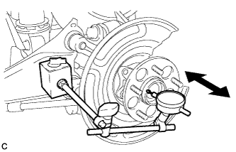 |
Using a dial indicator, check for looseness near the center of the rear axle hub.
| 4. INSPECT REAR AXLE HUB RUNOUT |
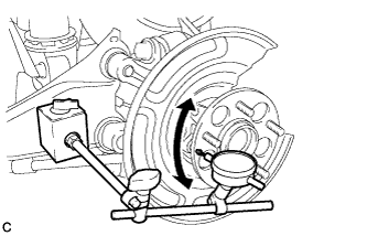 |
Using a dial indicator, check for runout on the surface of the rear axle hub outside the rear axle hub bolt.
| 5. INSTALL REAR DISC |
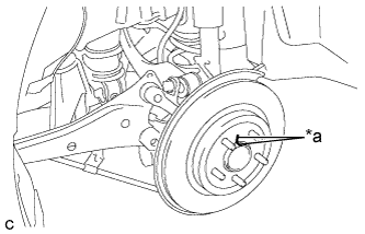 |
Align the matchmarks of the disc and axle hub, and install the disc.
| *a | Matchmark |
| 6. INSTALL REAR DISC BRAKE CALIPER ASSEMBLY |
Install the rear disc brake caliper assembly with the 2 bolts.
Install the rear flexible hose to the No. 2 flexible hose bracket with the bolt.
| 7. CONNECT NO. 3 PARKING BRAKE CABLE ASSEMBLY |
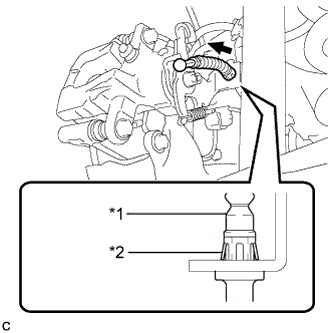 |
Install the No. 3 parking brake cable assembly to the rear disc brake cylinder assembly.
| *1 | No. 3 Parking Brake Cable Assembly |
| *2 | Clip |
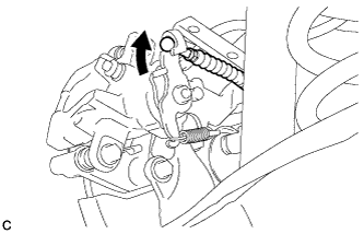 |
Connect the No. 3 parking brake cable assembly to the rear disc brake cylinder assembly.
Install the No. 3 parking brake cable assembly with the bolt.
| 8. INSTALL PARKING BRAKE LEVER PROTECTOR |
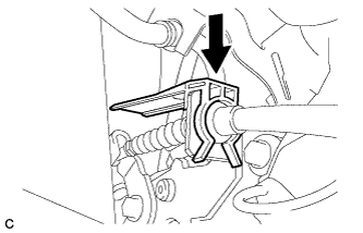 |
Install the parking brake lever protector to the No. 3 parking brake cable assembly.
| 9. INSTALL REAR SUSPENSION ARM COVER |
Insert the 2 claws of the rear suspension arm cover into the rear No. 2 suspension arm assembly.
Install the rear suspension arm cover with the 2 bolts.
| 10. ADJUST PARKING BRAKE |
| 11. INSTALL LOWER INSTRUMENT PANEL FINISH PANEL SUB-ASSEMBLY (for LHD) |
Connect each connector.
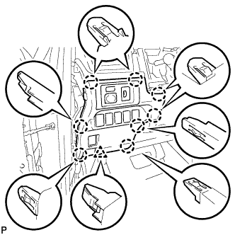 |
Engage the 8 claws and clip to install the lower instrument panel finish panel sub-assembly.
| 12. INSTALL INSTRUMENT SIDE PANEL LH (for LHD) |
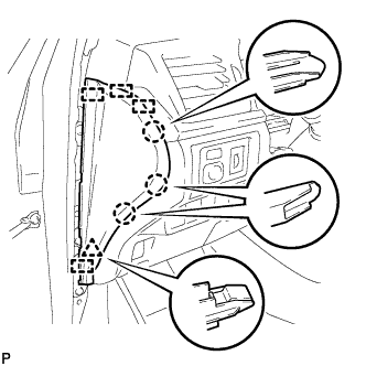 |
Engage the 4 guides, clip and 3 claws to install the instrument side panel LH.
| 13. INSTALL FRONT DOOR OPENING TRIM WEATHERSTRIP LH (for LHD) |
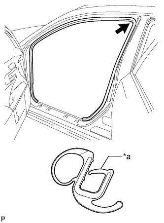 |
Align the alignment mark (orange) on the weatherstrip with the protruding portion on the body indicated by the arrow in the illustration, and install the front door opening trim weatherstrip LH.
| *a | Alignment Mark (Orange) |
| 14. INSTALL NO. 1 INSTRUMENT PANEL UNDER COVER SUB-ASSEMBLY (for LHD) |
Connect each connector.
Engage the clamp.
Engage the clip.
Install the No. 1 instrument panel under cover sub-assembly with the 2 screws <E>.
| 15. INSTALL NO. 2 AIR DUCT SUB-ASSEMBLY (for RHD) |
Engage the 2 claws to install the No. 2 air duct sub-assembly.
| 16. INSTALL NO. 1 INSTRUMENT PANEL UNDER COVER SUB-ASSEMBLY (for RHD) |
Connect each connector.
Engage the clamp.
Engage the 2 clips.
Install the No. 1 instrument panel under cover sub-assembly with the screw <E>.
| 17. INSTALL REAR WHEEL |
| 18. CONNECT CABLE TO NEGATIVE AUXILIARY BATTERY TERMINAL |
Connect the cable to the negative (-) auxiliary battery terminal (Click here).
Connect the reservoir level switch connector.
Clear the DTCs (Click here).
| 19. CHECK FOR SPEED SENSOR SIGNAL |
