REAR AXLE CARRIER > INSTALLATION |
| 1. INSTALL REAR AXLE CARRIER SUB-ASSEMBLY |
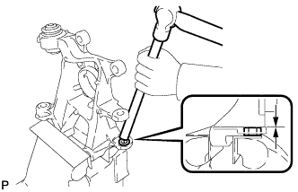 |
Hold the rear axle carrier sub-assembly between aluminum plates in a vise.
Using a brass bar and a hammer, push out the bushing until it is positioned as shown in the illustration.
Use a jack and wooden block to keep the rear No. 2 suspension arm assembly level.
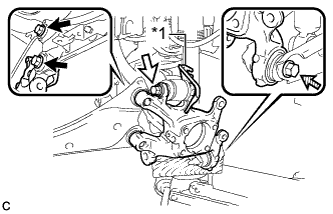 |
Temporarily install the rear axle carrier sub-assembly to the rear No. 2 suspension arm assembly with the bolt (C) and nut.
| *1 | No. 2 Flexible Hose Bracket |
 | Bolt (A) |
 | Bolt (B) |
 | Bolt (C) |
Temporarily install the rear axle carrier sub-assembly and No. 2 flexible hose bracket to the rear upper control arm assembly with the bolt (B) and nut.
Install the rear axle carrier sub-assembly to the rear trailing arm assembly with the 2 bolts (A).
Fully tighten the bolt (B) and bolt (C).
Slowly lower the rear No. 2 suspension arm assembly.
| 2. TEMPORARILY TIGHTEN REAR NO. 1 SUSPENSION ARM ASSEMBLY |
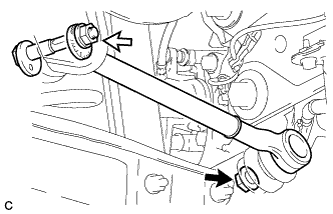 |
Temporarily tighten the rear No. 1 suspension arm assembly to the rear axle assembly with a new nut (A).
| Nut (A) |
| Nut (B) |
Using the rear suspension toe adjust cam sub-assembly, No. 2 camber adjust cam and nut (B), temporarily install the rear No. 1 suspension arm assembly to the rear suspension member sub-assembly.
Fully tighten the nut (A).
| 3. INSTALL REAR AXLE HUB AND BEARING ASSEMBLY |
Install the rear axle hub and bearing assembly and rear disc brake dust cover sub-assembly to the rear axle carrier sub-assembly with the 4 bolts.
| 4. INSTALL REAR HEIGHT CONTROL SENSOR SUB-ASSEMBLY (w/ Height Control Sensor) |
Engage the 2 guides and install the rear height control sensor sub-assembly with the 2 bolts.
Connect the connector.
Engage the clamp.
| 5. CONNECT REAR SPEED SENSOR WIRE |
Connect the rear speed sensor wire connector to the rear speed sensor.
| 6. INSTALL REAR DISC |
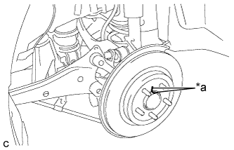 |
Align the matchmarks of the disc and axle hub, and install the disc.
| *a | Matchmark |
| 7. INSTALL REAR DISC BRAKE CALIPER ASSEMBLY |
Install the rear disc brake caliper assembly with the 2 bolts.
Install the rear flexible hose to the No. 2 flexible hose bracket with the bolt.
| 8. CONNECT NO. 3 PARKING BRAKE CABLE ASSEMBLY |
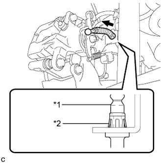 |
Install the No. 3 parking brake cable assembly to the rear disc brake cylinder assembly.
| *1 | No. 3 Parking Brake Cable Assembly |
| *2 | Clip |
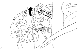 |
Connect the No. 3 parking brake cable assembly to the rear disc brake cylinder assembly.
Install the No. 3 parking brake cable assembly with the bolt.
| 9. INSTALL PARKING BRAKE LEVER PROTECTOR |
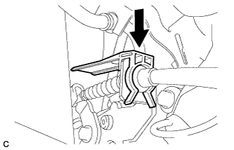 |
Install the parking brake lever protector to the No. 3 parking brake cable assembly.
| 10. ADJUST PARKING BRAKE |
| 11. INSTALL LOWER INSTRUMENT PANEL FINISH PANEL SUB-ASSEMBLY (for LHD) |
Connect each connector.
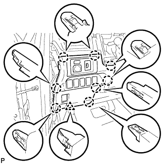 |
Engage the 8 claws and clip to install the lower instrument panel finish panel sub-assembly.
| 12. INSTALL INSTRUMENT SIDE PANEL LH (for LHD) |
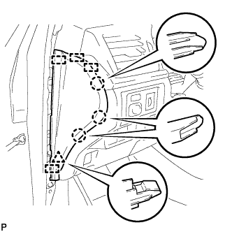 |
Engage the 4 guides, clip and 3 claws to install the instrument side panel LH.
| 13. INSTALL FRONT DOOR OPENING TRIM WEATHERSTRIP LH (for LHD) |
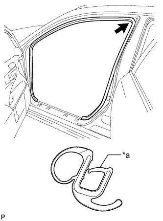 |
Align the alignment mark (orange) on the weatherstrip with the protruding portion on the body indicated by the arrow in the illustration, and install the front door opening trim weatherstrip LH.
| *a | Alignment Mark (Orange) |
| 14. INSTALL NO. 1 INSTRUMENT PANEL UNDER COVER SUB-ASSEMBLY (for LHD) |
Connect each connector.
Engage the clamp.
Engage the clip.
Install the No. 1 instrument panel under cover sub-assembly with the 2 screws <E>.
| 15. INSTALL NO. 2 AIR DUCT SUB-ASSEMBLY (for RHD) |
Engage the 2 claws to install the No. 2 air duct sub-assembly.
| 16. INSTALL NO. 1 INSTRUMENT PANEL UNDER COVER SUB-ASSEMBLY (for RHD) |
Connect each connector.
Engage the clamp.
Engage the 2 clips.
Install the No. 1 instrument panel under cover sub-assembly with the screw <E>.
| 17. INSTALL REAR FLOOR SIDE MEMBER COVER (w/ Floor Under Cover) |
for LH Side:
Install the rear floor side member cover LH with the 2 bolts, nut and 2 clips.
for RH Side:
Install the rear floor side member cover RH with the bolt, nut and 2 clips.
| 18. INSTALL REAR SUSPENSION ARM COVER |
Insert the 2 claws of the rear suspension arm cover into the rear No. 2 suspension arm assembly.
Install the rear suspension arm cover with the 2 bolts.
| 19. INSTALL REAR WHEEL |
| 20. FULLY TIGHTEN REAR NO. 1 SUSPENSION ARM ASSEMBLY |
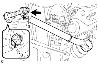 |
Align the matchmarks on the No. 2 camber adjust cam, rear suspension toe adjust cam sub-assembly and rear suspension member sub-assembly.
| *a | Matchmarks |
Fully tighten the nut to install the rear No. 1 suspension arm assembly.
| 21. CONNECT CABLE TO NEGATIVE AUXILIARY BATTERY TERMINAL |
Connect the cable to the negative (-) auxiliary battery terminal (Click here).
Connect the reservoir level switch connector.
Clear the DTCs (Click here).
| 22. INSPECT AND ADJUST REAR WHEEL ALIGNMENT |
| 23. HEIGHT CONTROL SENSOR SIGNAL INITIALIZATION (w/ Height Control Sensor) |
| 24. INSPECT AND ADJUST HEADLIGHT AIMING (w/ Height Control Sensor) |
| 25. CHECK FOR SPEED SENSOR SIGNAL |
