POWER DOOR LOCK CONTROL SYSTEM > Only Back Door cannot be Opened |
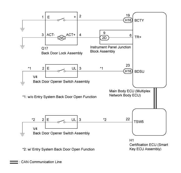
| 1.SYSTEM CHECK |
Check the vehicle specification.
| Result | Proceed to |
| w/o Entry System Back Door Open Function | A |
| w/ Entry System Back Door Open Function | B |
|
| ||||
| A | |
 |
| 2.CHECK POWER DOOR LOCK OPERATION (BASIC FUNCTION) |
Check the power door lock basic function (Click here).
|
| ||||
| OK | |
|
| 3.READ VALUE USING INTELLIGENT TESTER (DOOR LOCK STATUS) |
Unlock all doors.
Connect the intelligent tester to the DLC3.
Turn the power switch on (IG).
Turn the intelligent tester on.
Enter the following menus: Body / Main Body / Data List.
Read the Data List according to the display on the intelligent tester.
| Tester Display | Measurement Item/Range | Normal Condition | Diagnostic Note |
| Back Door Open | Back door lock/Permit or Prohibt | Permit: Back door unlocked Prohibt: Back door locked | - |
|
| ||||
| OK | |
|
| 4.PERFORM ACTIVE TEST USING INTELLIGENT TESTER |
Connect the intelligent tester to the DLC3.
Turn the power switch on (IG).
Turn the intelligent tester on.
Enter the following menus: Body / Main Body / Active Test.
Perform the Active Test according to the display on the intelligent tester.
| Tester Display | Test Part | Control Range | Diagnostic Note |
| Trunk and Back-Door Open | Operate back door lock motor | ON or OFF | - |
|
| ||||
| OK | |
|
| 5.READ VALUE USING INTELLIGENT TESTER |
Connect the intelligent tester to the DLC3.
Turn the power switch on (IG).
Turn the intelligent tester on.
Enter the following menus: Body / Main Body / Data List.
Read the Data List according to the display on the intelligent tester.
| Tester Display | Measurement Item/Range | Normal Condition | Diagnostic Note |
| Back Door Open Handle SW | Back door opener switch signal/ON or OFF | ON: Back door opener switch pushed OFF: Back door opener switch not pushed | - |
|
| ||||
| OK | ||
 | ||
| ||
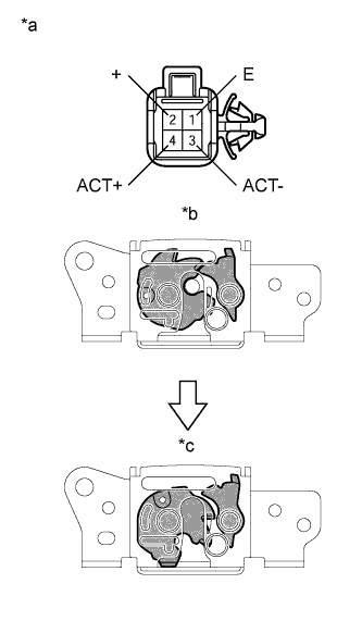
| 6.INSPECT BACK DOOR LOCK ASSEMBLY |
 |
Remove the back door lock assembly (Click here).
Check the operation of the door lock motor.
Move the door lock to the lock position.
Apply auxiliary battery voltage to the door lock motor and check the operation of the door lock motor.
| Connection | Result |
| Auxiliary battery positive (+) → Terminal 4 (ACT+) Auxiliary battery negative (-) → Terminal 3 (ACT-) | Unlocks |
Check the operation of the door courtesy switch.
Measure the resistance according to the value(s) in the table below.
| Tester Connection | Switch Condition | Specified Condition |
| 1 (E) - 2 (+) | Locked | 10 kΩ or higher |
| 1 (E) - 2 (+) | Unlocked | Below 1 Ω |
| *a | Component without harness connected (Back Door Lock Assembly) |
| *b | Lock |
| *c | Unlock |
|
| ||||
| OK | |
|
| 7.CHECK HARNESS AND CONNECTOR (BACK DOOR LOCK ASSEMBLY - MAIN BODY ECU) |
Disconnect the main body ECU (multiplex network body ECU) connector.
Disconnect the instrument panel junction block assembly connector.
Measure the resistance according to the value(s) in the table below.
| Tester Connection | Condition | Specified Condition |
| Q17-4 (ACT+) - 2D-9 (TR+) | Always | Below 1 Ω |
| Q17-4 (ACT+) - Body ground | Always | 10 kΩ or higher |
| Q17-2 (+) - H16-19 (BCTY) | Always | Below 1 Ω |
| Q17-2 (+) - Body ground | Always | 10 kΩ or higher |
| Q17-3 (ACT-) - Body ground | Always | Below 1 Ω |
| Q17-1 (E) - Body ground | Always | Below 1 Ω |
|
| ||||
| OK | |
|
| 8.REPLACE INSTRUMENT PANEL JUNCTION BLOCK ASSEMBLY |
Replace the instrument panel junction block assembly (Click here).
| NEXT | |
|
| 9.CHECK BACK DOOR OPEN OPERATION |
Check that the back door can be opened.
|
| ||||
| OK | ||
| ||
| ||
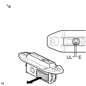
| 10.INSPECT BACK DOOR OPENER SWITCH ASSEMBLY |
 |
Remove the back door opener switch assembly (Click here).
Check the operation of the opener switch.
Measure the resistance according to the value(s) in the table below.
| Tester Connection | Switch Condition | Specified Condition |
| 2 (E) - 3 (UL) | Back door opener switch not pushed | 10 kΩ or higher |
| 2 (E) - 3 (UL) | Back door opener switch pushed | Below 1 Ω |
| *a | Component without harness connected (Back Door Opener Switch Assembly) |
|
| ||||
| OK | |
|
| 11.CHECK HARNESS AND CONNECTOR (BACK DOOR OPENER SWITCH ASSEMBLY - MAIN BODY ECU) |
Disconnect the main body ECU (multiplex network body ECU) connector.
Measure the resistance according to the value(s) in the table below.
| Tester Connection | Condition | Specified Condition |
| V4-3 (UL) - H16-23 (BDSU) | Always | Below 1 Ω |
| V4-3 (UL) - Body ground | Always | 10 kΩ or higher |
| V4-2 (E) - Body ground | Always | Below 1 Ω |
|
| ||||
| OK | ||
| ||
| ||


