REAR VIEW MONITOR SYSTEM > Image from Camera for Rear View Monitor is Abnormal |
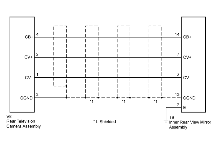
| 1.CHECK HARNESS AND CONNECTOR (INNER REAR VIEW MIRROR - REAR TELEVISION CAMERA) |
Disconnect the T9 connector from the inner rear view mirror assembly.
Disconnect the V8 connector from the rear television camera assembly.
Measure the resistance according to the value(s) in the table below.
| Tester Connection | Condition | Specified Condition |
| T9-7 (CV+) - V8-2 (CV+) | Always | Below 1 Ω |
| T9-14 (CB+) - V8-4 (CB+) | Always | Below 1 Ω |
| T9-6 (CV-) - V8-1 (CV-) | Always | Below 1 Ω |
| T9-13 (CGND) - V8-3 (CGND) | Always | Below 1 Ω |
| T9-7 (CV+) - Body ground | Always | 10 kΩ or higher |
| T9-14 (CB+) - Body ground | Always | 10 kΩ or higher |
| T9-6 (CV-) - Body ground | Always | 10 kΩ or higher |
| T9-13 (CGND) - Body ground | Always | 10 kΩ or higher |
|
| ||||
| OK | |
 |
| 2.CHECK INNER REAR VIEW MIRROR ASSEMBLY |
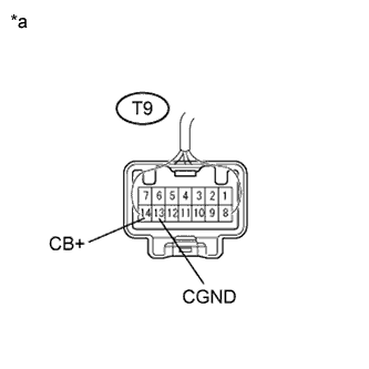 |
Reconnect the T9 connector to the inner rear view mirror assembly.
Measure the voltage according to the value(s) in the table below.
| Tester Connection | Condition | Specified Condition |
| T9-14 (CB+) - T9-13 (CGND) | Power switch on (READY) Reverse (R) selected | 5.5 to 7.0 V |
| *a | Component with harness connected (Inner Rear View Mirror Assembly) |
|
| ||||
| OK | |
|
| 3.CHECK REAR TELEVISION CAMERA ASSEMBLY |
Reconnect the V8 connector to the rear television camera assembly.
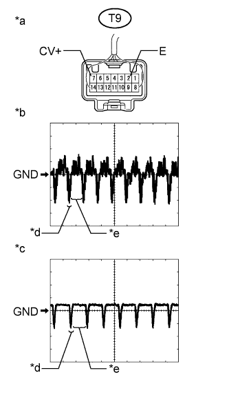 |
Check the waveform of the rear television camera assembly using an oscilloscope.
| Item | Content |
| Terminal No. (Symbol) | T9-7 (CV+) - T9-2 (E) |
| Tool Setting | 200 mV/DIV., 50 μsec./DIV. |
| Condition | Power switch on (READY), reverse (R) selected |
| *a | Component with harness connected (Inner Rear View Mirror Assembly) |
| *b | Waveform 1 (camera lens is not covered, displaying an image) |
| *c | Waveform 2 (camera lens is covered, blacking out the screen) |
| *d | Synchronization Signal |
| *e | Video Waveform |
|
| ||||
| OK | ||
 | ||
| ||

