STOP LIGHT CONTROL RELAY > INSPECTION |
| 1. INSPECT STOP LIGHT CONTROL ECU ASSEMBLY (w/ Emergency Brake Signal) |
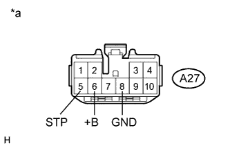 |
Disconnect the A27 stop light control ECU assembly connector.
Measure the voltage according to the value(s) in the table below.
| Tester Connection | Switch Condition | Specified Condition |
| A27-5 (STP) - Body ground | Power switch off and Brake pedal released | Below 1 V |
| Power switch off and Brake pedal depressed | 11 to 14 V | |
| A27-6 (+B) - Body ground | Power switch off | 11 to 14 V |
| *a | Front view of wire harness connector (to Stop Light Control ECU Assembly) |
Measure the resistance according to the value(s) in the table below.
| Tester Connection | Condition | Specified Condition |
| A27-8 (GND) - Body ground | Always | Below 1 Ω |
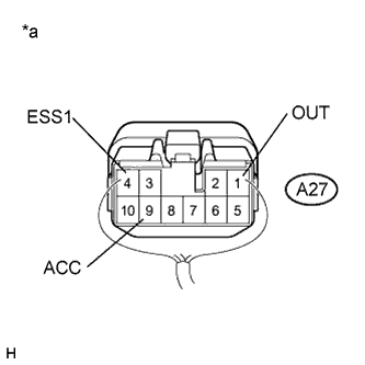 |
Reconnect the A27 stop light control ECU assembly connector.
Measure the voltage according to the value(s) in the table below.
| Tester Connection | Switch Condition | Specified Condition |
| A27-1 (OUT) - Body ground | Power switch off and Brake pedal released | Below 1 V |
| Power switch off and Brake pedal depressed | 11 to 14 V | |
| A27-4 (ESS1) - Body ground | Power switch off | 11 to 14 V |
| A27-9 (ACC) - Body ground | Power switch on (ACC) | 11 to 14 V |
| *a | Component without harness connected (Stop Light Control ECU Assembly) |
| 2. INSPECT STOP LIGHT CONTROL ECU ASSEMBLY (w/o Emergency Brake Signal) |
|
Disconnect the A27 stop light control ECU assembly connector.
Measure the voltage according to the value(s) in the table below.
| Tester Connection | Switch Condition | Specified Condition |
| A27-5 (STP) - Body ground | Power switch off and Brake pedal released | Below 1 V |
| Power switch off and Brake pedal depressed | 11 to 14 V | |
| A27-6 (+B) - Body ground | Power switch off | 11 to 14 V |
| *a | Front view of wire harness connector (to Stop Light Control ECU Assembly) |
Measure the resistance according to the value(s) in the table below.
| Tester Connection | Condition | Specified Condition |
| A27-8 (GND) - Body ground | Always | Below 1 Ω |
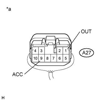 |
Reconnect the A27 stop light control ECU assembly connector.
Measure the voltage according to the value(s) in the table below.
| Tester Connection | Switch Condition | Specified Condition |
| A27-1 (OUT) - Body ground | Power switch off and Brake pedal released | Below 1 V |
| Power switch off and Brake pedal depressed | 11 to 14 V | |
| A27-9 (ACC) - Body ground | Power switch off | 11 to 14 V |
| *a | Component without harness connected (Stop Light Control ECU Assembly) |
