AUDIO AND VISUAL SYSTEM (w/ Navigation System) > Sound Signal Circuit between Radio Receiver and Stereo Jack Adapter |
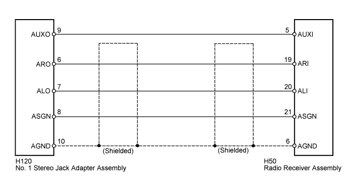
| 1.CHECK HARNESS AND CONNECTOR (RADIO RECEIVER ASSEMBLY - NO. 1 STEREO JACK ADAPTER ASSEMBLY) |
Disconnect the No. 1 stereo jack adapter assembly connector and radio receiver assembly connector.
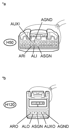 |
Measure the resistance according to the value(s) in the table below.
| Tester Connection | Condition | Specified Condition |
| H120-9 (AUXO) - H50-5 (AUXI) | Always | Below 1 Ω |
| H120-8 (ASGN) - H50-21 (ASGN) | Always | Below 1 Ω |
| H120-6 (ARO) - H50-19 (ARI) | Always | Below 1 Ω |
| H120-7 (ALO) - H50-20 (ALI) | Always | Below 1 Ω |
| H120-10 (AGND) - H50-6 (AGND) | Always | Below 1 Ω |
| H120-9 (AUXO) - Body ground | Always | 10 kΩ or higher |
| H120-8 (ASGN) - Body ground | Always | 10 kΩ or higher |
| H120-6 (ARO) - Body ground | Always | 10 kΩ or higher |
| H120-7 (ALO) - Body ground | Always | 10 kΩ or higher |
| H120-10 (AGND) - Body ground | Always | 10 kΩ or higher |
| *a | Front view of wire harness connector (to Radio Receiver Assembly) |
| *b | Front view of wire harness connector (to No. 1 Stereo Jack Adapter Assembly) |
|
| ||||
| OK | ||
 | ||
| ||

