PERSONAL LIGHT > INSPECTION |
| 1. INSPECT MAP LIGHT ASSEMBLY |
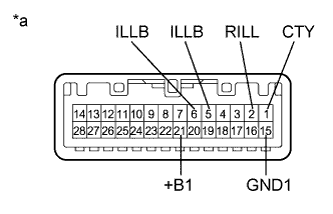 |
Inspect the interior light door switch.
Measure the resistance according to the value(s) in the table below.
| Tester Connection | Condition | Specified Condition |
| 1 (CTY) - 2 (RILL) | Interior light door switch OFF | 10 kΩ or higher |
| Interior light door switch ON | 10 kΩ or higher | |
| Interior light door switch DOOR | Below 1 Ω | |
| 15 (GND1) - 2 (RILL) | Interior light door switch OFF | 10 kΩ or higher |
| Interior light door switch ON | Below 1 Ω | |
| Interior light door switch DOOR | 10 kΩ or higher |
| *a | Component without harness connected (Map Light Assembly) |
Inspect the map lights.
Connect a positive (+) lead from the auxiliary battery to terminal 21 (+B1) and a negative (-) lead to terminal 15 (GND1) or 1 (CTY).
| Tester Connection | Condition | Specified Condition |
| 21 (+B1) - 1 (CTY) | Interior light door switch and map light switches OFF | Map light LH and RH do not come on |
| 21 (+B1) - 15 (GND1) | Interior light door switch and map light switches OFF | Map light LH and RH do not come on |
| 21 (+B1) - 15 (GND1) | Map light switch LH ON | Map light LH comes on |
| Map light switch RH ON | Map light RH comes on | |
| Map light switch LH OFF Map light switch RH OFF Interior light door switch ON | Map light LH and RH come on | |
| 21 (+B1) - 1 (CTY) | Map light switch LH OFF Map light switch RH OFF Interior light door switch DOOR | Map light LH and RH come on |
Inspect the center console spot light.
Connect a positive (+) lead from the auxiliary battery to terminal 21 (+B1) and a negative (-) lead to terminal 5 (ILLB) or 6 (ILLB).
| Tester Connection | Condition | Specified Condition |
| 21 (+B1) - 5 (ILLB) | Auxiliary battery positive (+) → Terminal 21 (+B1) Auxiliary battery positive (-) → Terminal 5 (ILLB) | Center console spot light (red) comes on |
| 21 (+B1) - 6 (ILLB) | Auxiliary battery positive (+) → Terminal 21 (+B1) Auxiliary battery positive (-) → Terminal 6 (ILLB) | Center console spot light (blue) comes on |
Measure the resistance according to the value(s) in the table below.
| Tester Connection | Condition | Specified Condition |
| 1 (CTY) - 2 (RILL) | Interior light door switch DOOR | Below 1 Ω |
