WINDOW DEFOGGER SYSTEM > Rear Window Defogger System does not Operate |
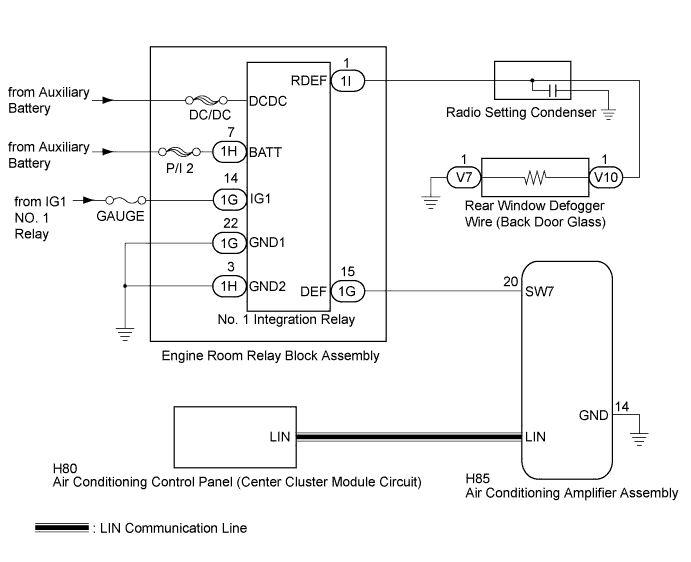
| 1.CHECK AIR CONDITIONING SYSTEM |
Check the air conditioning system.
|
| ||||
| OK | |
 |
| 2.PERFORM ACTIVE TEST USING INTELLIGENT TESTER (DEFOGGER RELAY) |
Connect the intelligent tester to the DLC3.
Turn the power switch on (IG).
Turn the intelligent tester on.
Enter the following menus: Body / Air Conditioner / Active Test.
Perform the Active Test according to the display on the intelligent tester.
| Tester Display | Test Part | Control Range | Diagnostic Note |
| Defogger Relay (Rear) | Rear window defogger | OFF or ON | - |
|
| ||||
| OK | ||
 | ||
| ||
| 3.CHECK HARNESS AND CONNECTOR (NO. 1 INTEGRATION RELAY - BATTERY AND BODY GROUND) |
Disconnect the 1G and 1H No. 1 integration relay connectors.
Measure the voltage and resistance according to the value(s) in the table below.
| Tester Connection | Condition | Specified Condition |
| 1H-7 (BATT) - Body ground | Power switch off | 11 to 14 V |
| 1G-14 (IG1) - Body ground | Power switch on (IG) | 11 to 14 V |
| 1G-14 (IG1) - Body ground | Power switch off | Below 1 V |
| Tester Connection | Condition | Specified Condition |
| 1G-22 (GND1) - Body ground | Always | Below 1 Ω |
| 1H-3 (GND2) - Body ground | Always | Below 1 Ω |
|
| ||||
| OK | |
|
| 4.CHECK HARNESS AND CONNECTOR (AIR CONDITIONING AMPLIFIER - NO. 1 INTEGRATION RELAY) |
Disconnect the H85 air conditioning amplifier assembly connector.
Measure the resistance according to the value(s) in the table below.
| Tester Connection | Condition | Specified Condition |
| H85-20 (SW7) - 1G-15 (DEF) | Always | Below 1 Ω |
| 1G-15 (DEF) - Body ground | Always | 10 kΩ or higher |
| H85-14 (GND) - Body ground | Always | Below 1 Ω |
|
| ||||
| OK | |
|
| 5.CHECK NO. 1 INTEGRATION RELAY |
Reconnect the 1G and 1H No. 1 integration relay connectors.
Measure the voltage according to the value(s) in the table below.
| Tester Connection | Condition | Specified Condition |
| H85-20 (SW7) - Body ground | Always | 11 to 14 V |
|
| ||||
| OK | |
|
| 6.CHECK AIR CONDITIONING AMPLIFIER ASSEMBLY |
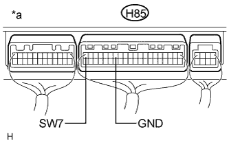 |
Reconnect the H85 air conditioning amplifier assembly connector.
Measure the voltage according to the value(s) in the table below.
| Tester Connection | Switch Condition | Specified Condition |
| H85-20 (SW7) - H85-14 (GND) | Power switch on (IG), rear window defogger switch off | 11 to 14 V |
| H85-20 (SW7) - H85-14 (GND) | Power switch on (IG), rear window defogger switch on | Below 1 V |
| *a | Rear view of wire harness connector (to Air Conditioning Amplifier Assembly) |
|
| ||||
| OK | |
|
| 7.INSPECT RADIO SETTING CONDENSER |
Remove the radio setting condenser (Click here).
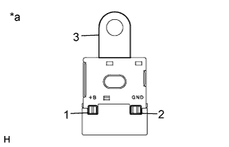 |
Measure the resistance of the radio setting condenser according to the value(s) in the table below.
| Tester Connection | Condition | Specified Condition |
| 1 - 2 | Always | 10 kΩ or higher |
| 2 - 3 | Always | 10 kΩ or higher |
| 1 - 3 | Always | 10 kΩ or higher |
| *a | Radio Setting Condenser |
|
| ||||
| OK | |
|
| 8.CHECK HARNESS AND CONNECTOR (NO. 1 INTEGRATION RELAY - REAR WINDOW DEFOGGER WIRE) |
Disconnect the V10 rear window defogger wire (back door glass) battery side connector.
Disconnect the 1I No. 1 integration relay connector.
Measure the resistance according to the value(s) in the table below.
| Tester Connection | Condition | Specified Condition |
| 1I-1 (RDEF) - Body ground | Always | 10 kΩ or higher |
| 1I-1 (RDEF) - V10-1 | Always | Below 1 Ω |
|
| ||||
| OK | |
|
| 9.CHECK NO. 1 INTEGRATION RELAY |
Reconnect the 1I No. 1 integration relay connector.
Measure the voltage according to the value(s) in the table below.
| Tester Connection | Switch Condition | Specified Condition |
| V10-1 - Body ground | Power switch on (IG), rear window defogger switch on | 11 to 14 V |
| V10-1 - Body ground | Power switch on (IG), rear window defogger switch off | Below 1 V |
|
| ||||
| OK | |
|
| 10.CHECK HARNESS AND CONNECTOR (REAR WINDOW DEFOGGER WIRE - BODY GROUND) |
Disconnect the V7 rear window defogger wire (back door glass) ground side connector.
Measure the resistance according to the value(s) in the table below.
| Tester Connection | Condition | Specified Condition |
| V7-1 - Body ground | Always | Below 1 Ω |
|
| ||||
| OK | ||
| ||
| ||
| 11.REPLACE NO. 1 INTEGRATION RELAY |
Replace the No. 1 integration relay (Click here).
| NEXT | |
|
| 12.CHECK WINDOW DEFOGGER SYSTEM |
Check the operation of the window defogger system.
|
| ||||
| OK | ||
| ||
| ||


