NAVIGATION SYSTEM (for HDD) > DVD Image Signal Circuit between Navigation ECU and Multi-display |
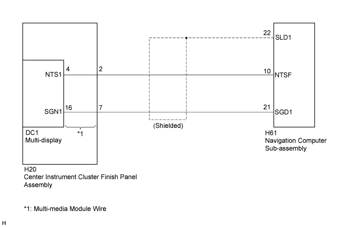
| 1.CHECK HARNESS AND CONNECTOR |
Disconnect the H61 navigation computer sub-assembly connector.
Disconnect the H20 multi-media module wire connector.
Measure the resistance according to the value(s) in the table below.
| Tester Connection | Condition | Specified Condition |
| H61-10 (NTSF) - H20-2 (NTS1) | Always | Below 1 Ω |
| H61-21 (SGD1) - H20-7 (SGN1) | Always | Below 1 Ω |
| H61-10 (NTSF) - Body ground | Always | 10 kΩ or higher |
| H61-21 (SGD1) - Body ground | Always | 10 kΩ or higher |
| H61-22 (SLD1) - Body ground | Always | 10 kΩ or higher |
|
| ||||
| OK | |
 |
| 2.INSPECT MULTI-MEDIA MODULE WIRE |
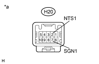 |
Disconnect the H20 multi-media module wire connector.
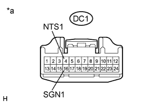 |
Disconnect the DC1 multi-media module wire connector.
Measure the resistance according to the value(s) in the table below.
| Tester Connection | Condition | Specified Condition |
| H20-2 (NTS1) - DC1-4 (NTS1) | Always | Below 1 Ω |
| H20-7 (SGN1) - DC1-16 (SGN1) | Always | Below 1 Ω |
| *a | Component without harness connected (Multi-media Module Wire) |
|
| ||||
| OK | |
|
| 3.INSPECT NAVIGATION COMPUTER SUB-ASSEMBLY (DVD IMAGE SIGNAL) |
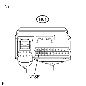 |
Reconnect the H61 navigation computer sub-assembly connector.
Check the waveform according to the table below.
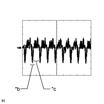 |
Oscilloscope waveform
| Item | Content |
| Measurement terminal | H61-10 (NTSF) - Body ground |
| Measurement setting | 200 mV/DIV., 10 μs/DIV. |
| Condition | DVD is playing on multi-display |
| *a | Component with harness connected (Navigation Computer Sub-assembly) |
| *b | Synchronization Signal |
| *c | Video Waveform |
|
| ||||
| OK | ||
 | ||
| ||

