PUSH-BUTTON START SYSTEM > Power Source Mode does not Change to ON (IG and ACC) |
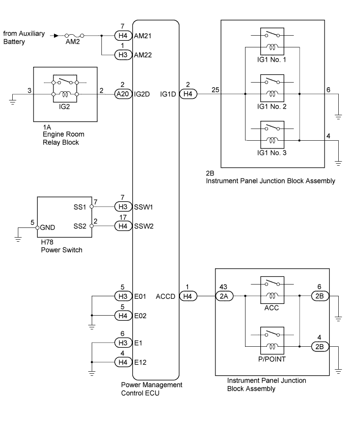
| Problem Symptom | Data List Item | Active Test Item |
| Power source mode does not change to on (IG) or on (ACC) | Power Source Control
| - |
| 1.READ VALUE USING INTELLIGENT TESTER (KEY CANCEL SWITCH) |
Turn the power switch off.
Connect the intelligent tester to the DLC3.
Turn the power switch on (IG).
Turn the intelligent tester on.
Enter the following menus: Body / Entry&Start / Data List.
Read the Data List according to the display on the intelligent tester.
| Tester Display | Measurement Item/Range | Normal Condition | Diagnostic Note |
| Auto Entry Cancel SW | Push-button start cancel function setting / OFF or ON | Mode status displayed ON: push-button start system canceled OFF: push-button start system not canceled | The default setting for the push-button start cancel function is OFF. If the customer requests that the push-button start system functions be canceled, the setting can be changed through the customize function (Click here). |
| Result | Proceed to |
| Push-button start cancel function is OFF | A |
| Push-button start cancel function is ON | B |
|
| ||||
| A | |
 |
| 2.CHECK HARNESS AND CONNECTOR (AUXILIARY BATTERY - POWER MANAGEMENT CONTROL ECU) |
Disconnect the H3 and H4 connectors from the power management control ECU.
Measure the voltage according to the value(s) in the table below.
| Tester Connection | Condition | Specified Condition |
| H3-1 (AM22) - Body ground | Always | 9.5 to 16 V |
| H4-7 (AM21) - Body ground | Always | 9.5 to 16 V |
|
| ||||
| OK | |
|
| 3.CHECK HARNESS AND CONNECTOR (POWER MANAGEMENT CONTROL ECU - BODY GROUND) |
Measure the resistance according to the value(s) in the table below.
| Tester Connection | Condition | Specified Condition |
| H3-5 (E01) - Body ground | Always | Below 1 Ω |
| H3-6 (E1) - Body ground | Always | Below 1 Ω |
| H4-4 (E12) - Body ground | Always | Below 1 Ω |
| H4-5 (E02) - Body ground | Always | Below 1 Ω |
|
| ||||
| OK | |
|
| 4.READ VALUE USING INTELLIGENT TESTER |
Reconnect the L5 and L6 connectors to the power management control ECU.
Read the Data List according to the display on the intelligent tester.
| Tester Display | Measurement Item/Range | Normal Condition | Diagnostic Note |
| Key Certification Waiting Timed Out | Key certification error detection/ No or Yes | No: Key certification error not detected Yes: Key certification error detected | - |
|
| ||||
| OK | |
|
| 5.READ VALUE USING INTELLIGENT TESTER |
Read the Data List according to the display on the intelligent tester.
| Tester Display | Measurement Item/Range | Normal Condition | Diagnostic Note |
| Start Switch1 | Start switch 1/ON or OFF | ON: Power switch pushed OFF: Power switch not pushed | - |
| Start Switch2 | Start switch 2/ON or OFF | ON: Power switch pushed OFF: Power switch not pushed | - |
|
| ||||
| OK | |
|
| 6.CHECK POWER MANAGEMENT CONTROL ECU |
Read the Data List according to the display on the intelligent tester.
| Tester Display | Measurement Item/Range | Normal Condition | Diagnostic Note |
| Power Supply Condition | Power supply condition/All OFF, ACC ON, IG1 ON, IG2 ON, ST ON | ALL OFF: All relays off ACC ON: ACC relay on IG1 ON: IG1 relay on IG2 ON: IG2 relay on ST ON: ST request signal on | - |
Measure the voltage while checking the Data List on the intelligent tester.
| Tester Connection | Condition | Specified Condition |
| H4-2 (IG1D) - Body ground | Power switch off | Below 1 V |
| H4-2 (IG1D) - Body ground | Power switch on (ACC) | Below 1 V |
| H4-2 (IG1D) - Body ground | Power switch on (IG) | Output voltage at terminal AM21 or AM22 is -2.5 V or more |
| A20-2 (IG2D) - Body ground | Power switch off | Below 1 V |
| A20-2 (IG2D) - Body ground | Power switch on (ACC) | Below 1 V |
| A20-2 (IG2D) - Body ground | Power switch on (IG) | Output voltage at terminal AM21 or AM22 is -2.5 V or more |
| H4-1 (ACCD) - Body ground | Power switch off | Below 1 V |
| H4-1 (ACCD) - Body ground | Power switch on (IG) | Output voltage at terminal AM21 or AM22 is -2.5 V or more |
| H4-1 (ACCD) - Body ground | Power switch on (ACC) | Output voltage at terminal AM21 or AM22 is -2.5 V or more |
|
| ||||
| OK | |
|
| 7.CONFIRMATION TEST |
Check that the power source mode becomes on (ACC) and on (IG) when the power switch is operated.
|
| ||||
| OK | ||
 | ||
| ||
| 8.INSPECT POWER SWITCH |
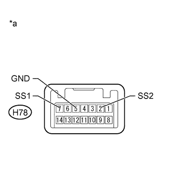 |
Remove the power switch (Click here).
Measure the resistance according to the value(s) in the table below.
| Tester Connection | Condition | Specified Condition |
| H78-7 (SS1) - H78-5 (GND) | Pushed | Below 1 Ω |
| H78-7 (SS1) - H78-5 (GND) | Not pushed | 10 kΩ or higher |
| H78-2 (SS2) - H78-5 (GND) | Pushed | Below 1 Ω |
| H78-2 (SS2) - H78-5 (GND) | Not pushed | 10 kΩ or higher |
| *a | Component without harness connected (Power Switch) |
|
| ||||
| OK | |
|
| 9.CHECK HARNESS AND CONNECTOR (POWER SWITCH - POWER MANAGEMENT CONTROL ECU AND BODY GROUND) |
Disconnect the H3 and H4 connectors from the power management control ECU.
Measure the resistance according to the value(s) in the table below.
| Tester Connection | Condition | Specified Condition |
| H4-17 (SSW2) - H78-2 (SS2) | Always | Below 1 Ω |
| H3-7 (SSW1) - H78-7 (SS1) | Always | Below 1 Ω |
| H4-17 (SSW2) - Body ground | Always | 10 kΩ or higher |
| H3-7 (SSW1) - Body ground | Always | 10 kΩ or higher |
|
| ||||
| OK | ||
| ||
| ||
| 10.CHECK FOR DTC |
Enter the following menus: Body / Power Source Control and Entry&Start / DTC.
Check for DTCs.
| Result | Proceed to |
The following DTCs are not output:
| A |
| DTC B2785 is not output but DTC B2287 is output. | B |
| DTCs other than B2287 are output. | C |
|
| ||||
|
| ||||
| C | ||
| ||
| ||


