ENTRY AND START SYSTEM (for Start Function) > Power Source Mode does not Change to ON (IG and ACC) |
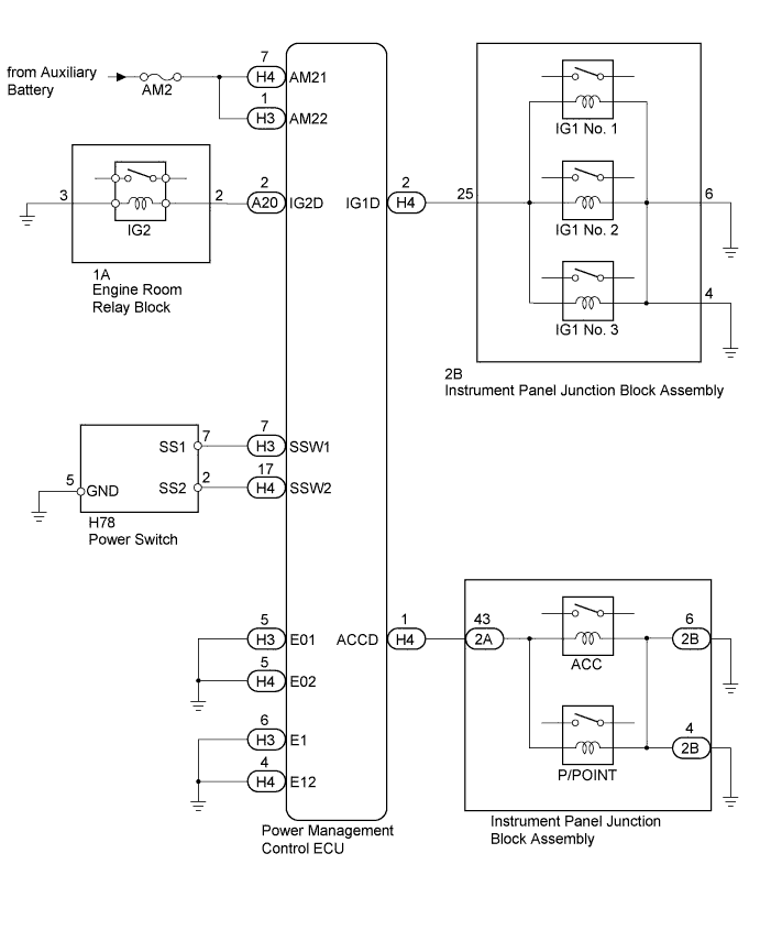
| Problem Symptom | Data List Item | Active Test Item |
| Power source mode does not change to on (IG) or on (ACC) | Power Source Control
| - |
| 1.CHECK HARNESS AND CONNECTOR (AUXILIARY BATTERY - POWER MANAGEMENT CONTROL ECU) |
Disconnect the H3 and H4 connectors from the power management control ECU.
Measure the voltage according to the value(s) in the table below.
| Tester Connection | Condition | Specified Condition |
| H3-1 (AM22) - Body ground | Always | 9.5 to 16 V |
| H4-7 (AM21) - Body ground | Always | 9.5 to 16 V |
|
| ||||
| OK | |
 |
| Go to step 4 |
| 2.CHECK HARNESS AND CONNECTOR (POWER MANAGEMENT CONTROL ECU - BODY GROUND) |
Measure the resistance according to the value(s) in the table below.
| Tester Connection | Condition | Specified Condition |
| H3-5 (E01) - Body ground | Always | Below 1 Ω |
| H3-6 (E1) - Body ground | Always | Below 1 Ω |
| H4-4 (E12) - Body ground | Always | Below 1 Ω |
| H4-5 (E02) - Body ground | Always | Below 1 Ω |
|
| ||||
| OK | |
|
| Go to step 5 |
| 3.READ VALUE USING INTELLIGENT TESTER |
Reconnect the L5 and L6 connectors to the power management control ECU.
Turn the power switch off.
Connect the intelligent tester to the DLC3.
Turn the power switch on (IG).
Turn the intelligent tester on.
Enter the following menus: Body / Power Source Control / Data List.
Read the Data List according to the display on the intelligent tester.
| Tester Display | Measurement Item/Range | Normal Condition | Diagnostic Note |
| Key Certification Waiting Timed Out | Key certification error detection/ No or Yes | No: Key certification error not detected Yes: Key certification error detected | - |
|
| ||||
| OK | |
|
| 4.READ VALUE USING INTELLIGENT TESTER |
Read the Data List according to the display on the intelligent tester.
| Tester Display | Measurement Item/Range | Normal Condition | Diagnostic Note |
| Start Switch1 | Start switch 1/ON or OFF | ON: Power switch pushed OFF: Power switch not pushed | - |
| Start Switch2 | Start switch 2/ON or OFF | ON: Power switch pushed OFF: Power switch not pushed | - |
|
| ||||
| OK | |
|
| 5.CHECK POWER MANAGEMENT CONTROL ECU |
Read the Data List according to the display on the intelligent tester.
| Tester Display | Measurement Item/Range | Normal Condition | Diagnostic Note |
| Power Supply Condition | Power supply condition/All OFF, ACC ON, IG1 ON, IG2 ON, ST ON | ALL OFF: All relays off ACC ON: ACC relay on IG1 ON: IG1 relay on IG2 ON: IG2 relay on ST ON: ST request signal on | - |
Measure the voltage while checking the Data List on the intelligent tester.
| Tester Connection | Condition | Specified Condition |
| H4-2 (IG1D) - Body ground | Power switch off | Below 1 V |
| H4-2 (IG1D) - Body ground | Power switch on (ACC) | Below 1 V |
| H4-2 (IG1D) - Body ground | Power switch on (IG) | Output voltage at terminal AM21 or AM22 is -2.5 V or more |
| A20-2 (IG2D) - Body ground | Power switch off | Below 1 V |
| A20-2 (IG2D) - Body ground | Power switch on (ACC) | Below 1 V |
| A20-2 (IG2D) - Body ground | Power switch on (IG) | Output voltage at terminal AM21 or AM22 is -2.5 V or more |
| H4-1 (ACCD) - Body ground | Power switch off | Below 1 V |
| H4-1 (ACCD) - Body ground | Power switch on (IG) | Output voltage at terminal AM21 or AM22 is -2.5 V or more |
| H4-1 (ACCD) - Body ground | Power switch on (ACC) | Output voltage at terminal AM21 or AM22 is -2.5 V or more |
|
| ||||
| OK | |
|
| 6.CONFIRMATION TEST |
Check that the power source mode becomes on (ACC) and on (IG) when the power switch is operated.
|
| ||||
| OK | ||
 | ||
| ||
| 7.INSPECT POWER SWITCH |
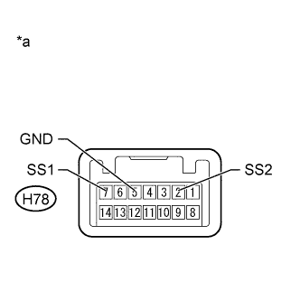 |
Remove the power switch (Click here).
Measure the resistance according to the value(s) in the table below.
| Tester Connection | Condition | Specified Condition |
| H78-7 (SS1) - H78-5 (GND) | Pushed | Below 1 Ω |
| H78-7 (SS1) - H78-5 (GND) | Not pushed | 10 kΩ or higher |
| H78-2 (SS2) - H78-5 (GND) | Pushed | Below 1 Ω |
| H78-2 (SS2) - H78-5 (GND) | Not pushed | 10 kΩ or higher |
| *a | Component without harness connected (Power Switch) |
|
| ||||
| OK | |
|
| 8.CHECK HARNESS AND CONNECTOR (POWER SWITCH - POWER MANAGEMENT CONTROL ECU AND BODY GROUND) |
Disconnect the H3 and H4 connectors from the power management control ECU.
Measure the resistance according to the value(s) in the table below.
| Tester Connection | Condition | Specified Condition |
| H4-17 (SSW2) - H78-2 (SS2) | Always | Below 1 Ω |
| H3-7 (SSW1) - H78-7 (SS1) | Always | Below 1 Ω |
| H4-17 (SSW2) - Body ground | Always | 10 kΩ or higher |
| H3-7 (SSW1) - Body ground | Always | 10 kΩ or higher |
|
| ||||
| OK | ||
| ||
| ||
| 9.CHECK FOR DTC |
Enter the following menus: Body / Power Source Control and Entry&Start / DTC.
Check for DTCs.
| Result | Proceed to |
The following DTCs are not output:
| A |
| DTC B2785 is not output but DTC B2287 is output. | B |
| DTCs other than B2287 are output. | C |
|
| ||||
|
| ||||
| C | ||
| ||
| ||


