HYBRID TRANSAXLE OIL SEAL > REPLACEMENT |
| 1. REMOVE FRONT WHEEL |
| 2. REMOVE REAR ENGINE UNDER COVER LH |
| 3. REMOVE REAR ENGINE UNDER COVER RH |
| 4. REMOVE NO. 1 ENGINE UNDER COVER |
| 5. DRAIN HYBRID TRANSAXLE FLUID |
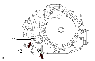 |
Using a 10 mm hexagon socket wrench, remove the filler plug and gasket.
| *1 | Filler Plug |
| *2 | Drain Plug |
Using a 10 mm hexagon socket wrench, remove the drain plug and gasket.
Using a 10 mm hexagon socket wrench, install the drain plug and a new gasket.
| 6. REMOVE FRONT AXLE SHAFT NUT |
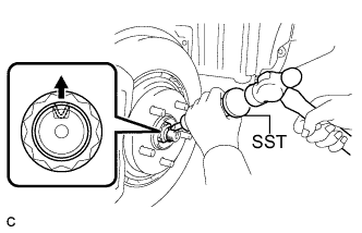 |
Using SST and a hammer, release the staked part of the front axle shaft nut.
While applying the brakes, remove the front axle shaft nut.
| 7. SEPARATE TIE ROD END SUB-ASSEMBLY |
Remove the clip and nut.
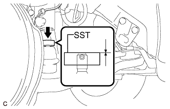 |
Install SST to the tie rod end.
Secure SST using a string.
Using SST, separate the tie rod end from the steering knuckle.
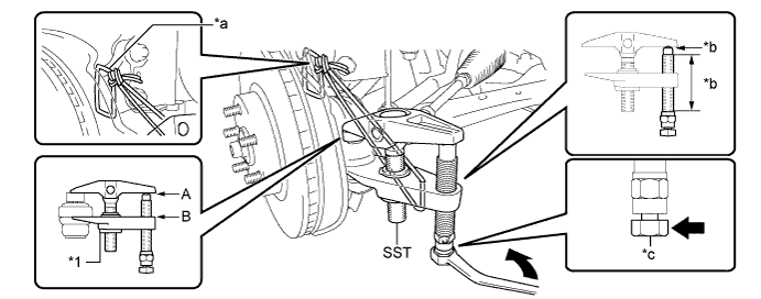
| *1 | Center Nut | - | - |
| *a | String | *b | Grease Application Area |
| *c | Place the wrench here. | - | - |
| 8. SEPARATE FRONT SPEED SENSOR |
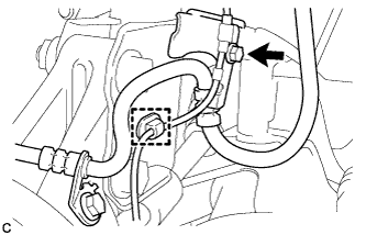 |
Remove the bolt and clamp, and separate the front speed sensor and front flexible hose from the front shock absorber with coil spring.
| 9. SEPARATE FRONT FLEXIBLE HOSE |
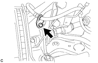 |
Remove the bolt and separate the front flexible hose from the steering knuckle.
| 10. SEPARATE FRONT STABILIZER LINK ASSEMBLY |
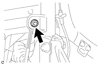 |
Remove the nut and separate the front stabilizer link assembly from the front shock absorber with coil spring.
| 11. SEPARATE FRONT LOWER NO. 1 SUSPENSION ARM SUB-ASSEMBLY |
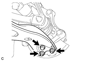 |
Remove the bolt and 2 nuts, and separate the front lower No. 1 suspension arm sub-assembly from the front lower ball joint assembly.
| 12. SEPARATE FRONT DRIVE SHAFT ASSEMBLY |
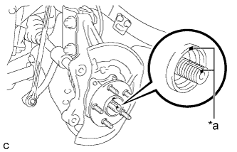 |
Put matchmarks on the front drive shaft assembly and front axle hub sub-assembly.
| *a | Matchmark |
Using a plastic hammer, separate the front drive shaft assembly from the front axle assembly. If it is difficult to separate, tap the end of the front drive shaft assembly using a brass bar and a hammer.
| 13. REMOVE FRONT DRIVE SHAFT ASSEMBLY |
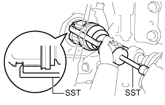 |
Using SST, remove the front drive shaft assembly.
| 14. REMOVE FRONT DRIVE SHAFT HOLE SNAP RING |
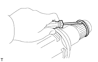 |
Using a screwdriver, remove the front drive shaft hole snap ring.
| 15. REMOVE HYBRID VEHICLE TRANSAXLE ASSEMBLY TYPE T OIL SEAL |
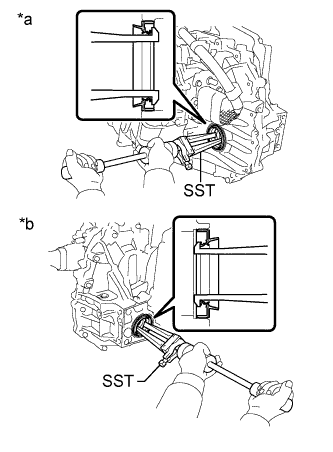 |
Using SST, remove the 2 oil seals.
| *a | LH Side |
| *b | RH Side |
| 16. INSTALL HYBRID VEHICLE TRANSAXLE ASSEMBLY TYPE T OIL SEAL |
Install a new LH side oil seal.
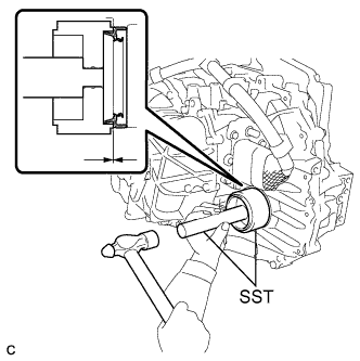 |
Using SST and a hammer, tap in a new oil seal.
Coat the lip of the oil seal with MP grease.
Install a new RH side oil seal.
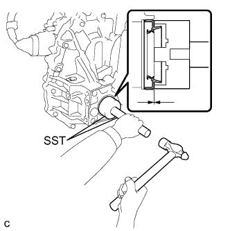 |
Using SST and a hammer, tap in a new oil seal.
Coat the lip of the oil seal with MP grease.
| 17. INSTALL FRONT DRIVE SHAFT HOLE SNAP RING |
Install a new front drive shaft hole snap ring to the front drive inboard joint assembly.
| 18. INSTALL FRONT DRIVE SHAFT ASSEMBLY |
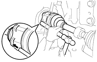 |
Align the inboard joint splines, and using a brass bar and a hammer, install the front drive shaft assembly.
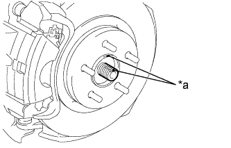 |
Align the matchmarks and install the front drive shaft assembly to the front axle hub sub-assembly.
| *a | Matchmark |
| 19. CONNECT FRONT LOWER NO. 1 SUSPENSION ARM SUB-ASSEMBLY |
Install the front lower No. 1 suspension arm sub-assembly to the front lower ball joint assembly with the bolt and 2 nuts.
| 20. INSTALL FRONT STABILIZER LINK ASSEMBLY |
Install the front stabilizer link assembly to the front shock absorber with coil spring with the nut.
| 21. INSTALL FRONT FLEXIBLE HOSE |
Install the front flexible hose to the steering knuckle with the bolt.
| 22. INSTALL FRONT SPEED SENSOR |
Install the front speed sensor and front flexible hose to the front shock absorber with coil spring with the bolt and clamp.
| 23. CONNECT TIE ROD END SUB-ASSEMBLY |
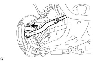 |
Connect the tie rod end sub-assembly LH to the steering knuckle with the nut.
Install a new clip.
| 24. INSTALL FRONT AXLE SHAFT NUT |
Clean the threaded parts on the front drive shaft assembly and a new front axle shaft nut using a non-residue solvent.
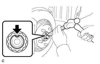 |
Using a socket wrench (30 mm), install the axle shaft nut.
Using a chisel and hammer, stake the front axle shaft nut.
| 25. ADD HYBRID TRANSAXLE FLUID |
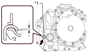 |
Add transaxle fluid until the fluid level is between 0 to 10 mm (0 to 0.394 in.) from the bottom lip of the filler plug opening.
| *1 | Filler Plug |
| *2 | Filler Nozzle |
After adding fluid, leave it for 30 seconds so that the fluid surface can become still again, and then check that the fluid level is between 0 to 10 mm (0 to 0.394 in.) from the bottom lip of the filler plug opening. (If the fluid level is too low, return to the Add Hybrid Transaxle Fluid procedure.)
| 26. INSPECT HYBRID TRANSAXLE FLUID |
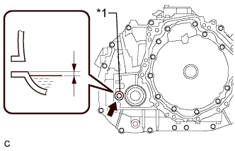 |
Using a 10 mm hexagon socket wrench, remove the filler plug and gasket.
| *1 | Filler Plug |
Check that the fluid level is between 0 to 10 mm (0 to 0.394 in.) from the bottom lip of the filler plug opening. (If the fluid level is too low, return to the Add Hybrid Transaxle Fluid procedure.)
Check for leaks if the quantity of transaxle fluid is low.
Using a 10 mm hexagon socket wrench, install the filler plug with a new gasket.
| 27. INSPECT FOR TRANSAXLE FLUID LEAK |
| 28. INSTALL FRONT WHEEL |
| 29. INSPECT AND ADJUST FRONT WHEEL ALIGNMENT |
| 30. INSTALL NO. 1 ENGINE UNDER COVER |
| 31. INSTALL REAR ENGINE UNDER COVER LH |
| 32. INSTALL REAR ENGINE UNDER COVER RH |
| 33. INSPECT SPEED SENSOR SIGNAL |
