ROOF HEADLINING > INSTALLATION |
| 1. INSTALL ROOF HEADLINING ASSEMBLY (w/o Sliding Roof) |
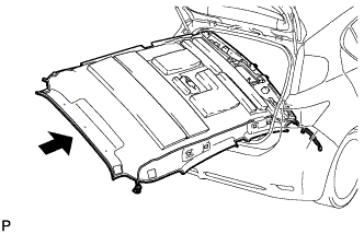 |
Put the roof headlining assembly into the vehicle through the back door.
Install the 3 clips.
Engage the 3 clamps and connect the 2 connectors to the front pillar LH.
Engage the 3 clamps and connect the connector to the front pillar RH.
Connect the connector to the rear pillar RH.
w/ EC Mirror
Connect the inner rear view mirror connector.
w/ Humidity Sensor
Connect the humidity sensor connector.
w/ Rain Sensor
Connect the rain sensor connector
| 2. INSTALL ROOF HEADLINING ASSEMBLY (w/ Sliding Roof) |
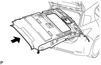 |
Put the roof headlining assembly into the vehicle through the back door.
Install the 3 clips.
Connect the connector to the sliding roof drive gear assembly.
Engage the 3 clamps and connect the 2 connectors to the front pillar LH.
Engage the 3 clamps and connect the connector to the front pillar RH.
Connect the connector to the rear pillar RH.
w/ EC Mirror
Connect the inner rear view mirror connector.
w/ Humidity Sensor
Connect the humidity sensor connector.
w/ Rain Sensor
Connect the rain sensor connector
| 3. INSTALL VISOR HOLDER |
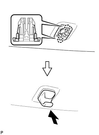 |
Engage the 2 claws.
Push in the visor holder as shown in the illustration.
| 4. INSTALL SLIDING ROOF OPENING TRIM MOULDING (w/ Sliding Roof) |
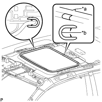 |
Align the alignment mark (green) on the moulding with the notch of the roof headlining to install the sliding roof opening trim moulding.
| *a | Notch |
| *b | Alignment Mark (Green) |
| 5. INSTALL VISOR ASSEMBLY LH |
Install the visor assembly LH with the 2 screws.
| 6. INSTALL VISOR BRACKET COVER (for LH Side) |
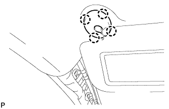 |
Engage the 4 claws to install the visor bracket cover LH.
| 7. INSTALL VISOR ASSEMBLY RH |
| 8. INSTALL VISOR BRACKET COVER (for RH Side) |
| 9. INSTALL ASSIST GRIP SUB-ASSEMBLY |
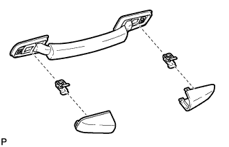 |
Assemble the assist grip sub-assembly as shown in the illustration.
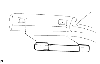 |
Install the assist grip sub-assembly.
| 10. INSTALL PROTECTOR (w/ Humidity Sensor) |
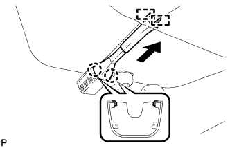 |
Engage the 2 claws and temporarily install the protector.
Slide the protector and engage the 2 guides as shown in the illustration to install the protector.
| 11. INSTALL RAIN SENSOR COVER (w/ Rain Sensor) |
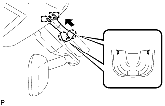 |
Engage the 2 claws and connect the rain sensor cover.
Engage the 2 guides and install the rain sensor cover as shown in the illustration.
| 12. INSTALL INNER REAR VIEW MIRROR STAY HOLDER COVER (w/ EC Mirror) |
w/o Rear View Monitor System:
Engage the 6 claws to install the inner rear view mirror stay holder cover.
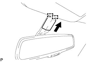 |
Engage the 2 guides to install the inner rear view mirror stay holder cover as shown in the illustration.
w/ Rear View Monitor System:
Engage the 2 claws to install the inner rear view mirror stay holder cover.
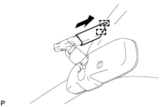 |
Engage the 2 guides to install the inner rear view mirror stay holder cover as shown in the illustration.
| 13. INSTALL NO. 1 ROOM LIGHT ASSEMBLY |
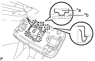 |
Align the switch parts shown in the illustration and engage the 4 claws to install the room light switch base to the No. 1 room light housing.
| *a | Switch Part of Room Light Switch Base |
| *b | Switch Part of No. 1 Room Light Housing |
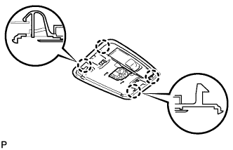 |
Engage the 4 claws to install the No. 1 room light housing.
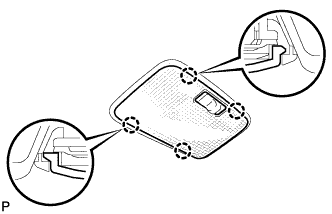 |
Engage the 4 claws to install the No. 1 room light lens.
| 14. INSTALL MAP LIGHT ASSEMBLY |
Connect the connector.
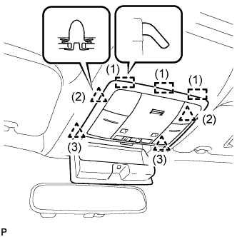 |
Engage the 3 guides and 4 clips to install the map light assembly as shown in the illustration.
Close the overhead console.
| 15. INSTALL BACK DOOR WEATHERSTRIP |
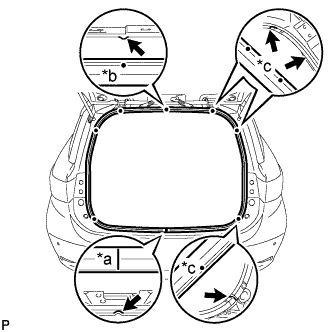 |
Install a new back door weatherstrip so that the alignment marks, joint and sections indicated by the arrows, are aligned as shown in the illustration.
| *a | Joint |
| *b | Alignment mark (Blue) |
| *c | Alignment mark (Pink) |
| 16. INSTALL UPPER INSTRUMENT PANEL ASSEMBLY |
| 17. INSTALL ROOF SIDE INNER GARNISH ASSEMBLY LH |
Pass the floor anchor of the rear seat outer belt assembly LH through the roof side inner garnish LH.
Engage the 8 clips to install the roof side inner garnish assembly LH.
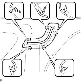 |
Engage the 2 guides.
Engage the 3 claws to connect the belt guide.
| 18. INSTALL DECK TRIM SIDE PANEL ASSEMBLY LH |
Engage the 4 claws and 3 clips.
Install the deck trim side panel assembly LH with the 3 screw.
| 19. CONNECT REAR SEAT OUTER BELT ASSEMBLY LH |
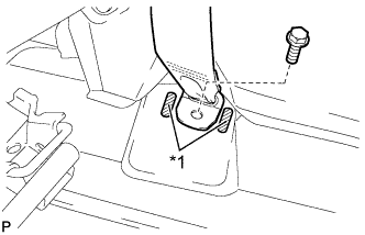 |
Connect the floor end of the rear seat outer belt assembly with the bolt.
| *1 | Protruding Part |
| 20. INSTALL TONNEAU COVER HOLDER CAP (for LH Side) |
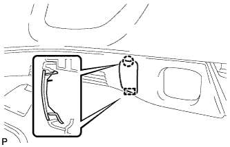 |
Engage the guide.
Engage the claw to install the tonneau cover holder cap.
| 21. INSTALL TONNEAU COVER HOOK (for LH Side) |
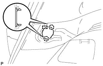 |
Engage the 2 claws and pin to install the tonneau cover hook.
| 22. INSTALL LUGGAGE HOLD BELT STRIKER ASSEMBLY (for LH Side) |
Engage the guide.
Install the luggage hold belt striker assembly with the bolt.
| 23. INSTALL ROPE HOOK ASSEMBLY (for LH Side) |
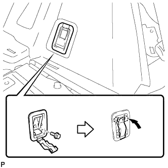 |
Install the rope hook assembly with the bolt.
Engage the 2 claws.
| 24. INSTALL REAR SEAT SIDE GARNISH LH |
Engage the 6 claws.
Install the rear seat side garnish LH with the clip.
| 25. INSTALL ROOF SIDE INNER GARNISH ASSEMBLY RH |
| 26. INSTALL DECK TRIM SIDE PANEL ASSEMBLY RH |
| 27. INSTALL REAR SEAT OUTER BELT ASSEMBLY RH |
| 28. INSTALL NO. 2 ROOM LIGHT ASSEMBLY |
Connect the connector.
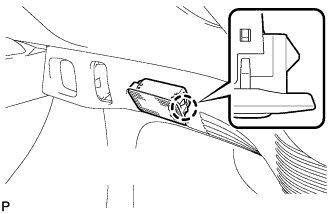 |
Engage the claw to install the No. 2 room light assembly.
| 29. INSTALL TONNEAU COVER HOLDER CAP (for RH Side) |
| 30. INSTALL TONNEAU COVER HOOK (for RH Side) |
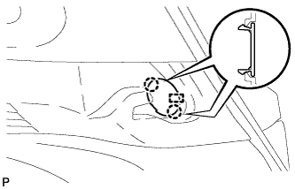 |
Engage the 2 claws and pin to install the tonneau cover hook.
| 31. INSTALL LUGGAGE HOLD BELT STRIKER ASSEMBLY (for RH Side) |
| 32. INSTALL ROPE HOOK ASSEMBLY (for RH Side) |
| 33. INSTALL REAR SEAT SIDE GARNISH RH |
| 34. INSTALL REAR SEAT SIDE COVER RH |
Engage the 3 claws and 2 clips to install the rear seat side cover RH.
| 35. INSTALL CENTER PILLAR UPPER GARNISH LH |
Pass the floor anchor of the front seat outer belt assembly LH through the center pillar upper garnish LH.
Engage the 2 clips.
Install the center pillar upper garnish LH with the screw.
| 36. INSTALL CENTER PILLAR LOWER GARNISH LH |
Engage the 4 claws and 2 clips to install the center pillar lower garnish LH.
| 37. CONNECT FRONT SEAT OUTER BELT ASSEMBLY LH |
Install the floor end of the front seat outer belt assembly with the bolt.
Check if the ELR locks.
With the belt assembly installed, check that the belt locks when it is pulled out quickly.
| 38. INSTALL LAP BELT OUTER ANCHOR COVER (for LH Side) |
Engage the 3 claws to install the lap belt outer anchor cover.
| 39. INSTALL REAR DOOR OPENING TRIM WEATHERSTRIP LH |
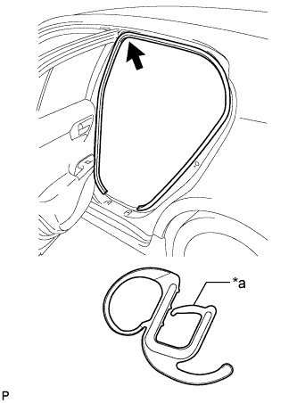 |
Align the alignment mark (purple) on the weatherstrip with the protruding portion on the body indicated by the arrow in the illustration, and install the rear door opening trim weatherstrip LH.
| *a | Alignment Mark (Purple) |
| 40. INSTALL REAR DOOR SCUFF PLATE LH |
Engage the 4 claws, 2 guides and 2 clips to install the rear door scuff plate LH.
| 41. INSTALL FRONT PILLAR GARNISH LH |
Remove the protective cover.
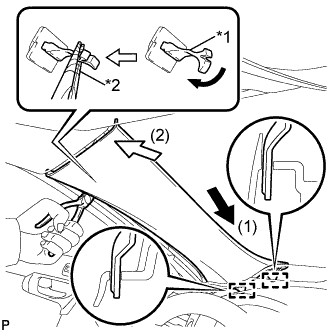 |
Make sure that the front pillar garnish clip is not damaged.
| *1 | Front Pillar Garnish Clip |
| *2 | Protective Tape |
Engage the 2 guides by moving the garnish in the direction indicated by the arrow (1).
Turn the end of the front pillar garnish clip 90° with needle-nosed pliers and install it to the front pillar garnish LH.
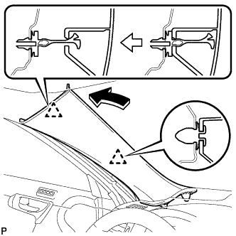 |
Engage the 2 clips to install the front pillar garnish LH.
| 42. INSTALL FRONT DOOR OPENING TRIM WEATHERSTRIP LH |
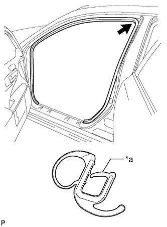 |
Align the alignment mark (orange) on the weatherstrip with the protruding portion on the body indicated by the arrow in the illustration, and install the front door opening trim weatherstrip LH.
| *a | Alignment Mark (Orange) |
| 43. INSTALL COWL SIDE TRIM SUB-ASSEMBLY LH |
Engage the claw and clip.
Install the cowl side trim sub-assembly LH with the clip.
| 44. INSTALL NO. 2 INSTRUMENT PANEL UNDER COVER SUB-ASSEMBLY (for RHD) |
Connect the connector.
Engage the clamp.
Engage the 2 guides, claw and 2 clips to install the No. 2 instrument panel under cover sub-assembly.
| 45. INSTALL FRONT DOOR SCUFF PLATE LH |
Engage the 4 claws, 2 guides and 4 clips to install the front door scuff plate LH.
| 46. INSTALL CENTER PILLAR UPPER GARNISH RH |
| 47. INSTALL CENTER PILLAR LOWER GARNISH RH |
| 48. CONNECT FRONT SEAT OUTER BELT ASSEMBLY RH |
| 49. INSTALL LAP BELT OUTER ANCHOR COVER (for RH Side) |
| 50. INSTALL REAR DOOR OPENING TRIM WEATHERSTRIP RH |
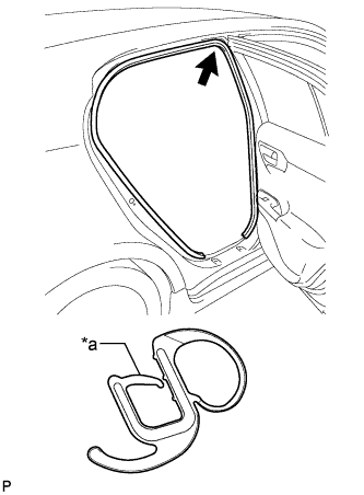 |
Align the alignment mark (yellow green) on the weatherstrip with the protruding portion on the body indicated by the arrow in the illustration, and install the rear door opening trim weatherstrip RH.
| *a | Alignment Mark (Yellow green) |
| 51. INSTALL REAR DOOR SCUFF PLATE RH |
| 52. INSTALL FRONT PILLAR GARNISH RH |
| 53. INSTALL FRONT DOOR OPENING TRIM WEATHERSTRIP RH |
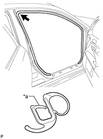 |
Align the alignment mark (light blue) on the weatherstrip with the protruding portion on the body indicated by the arrow in the illustration, and install the front door opening trim weatherstrip RH.
| *a | Alignment Mark (Light blue) |
| 54. INSTALL COWL SIDE TRIM SUB-ASSEMBLY RH |
| 55. INSTALL FRONT DOOR SCUFF PLATE RH |
| 56. INSTALL FRONT SEAT ASSEMBLY |
| 57. INSTALL REAR DECK TRIM COVER |
Engage the 4 clips to install the rear deck trim cover.
| 58. INSTALL DECK TRIM SERVICE HOLE COVER |
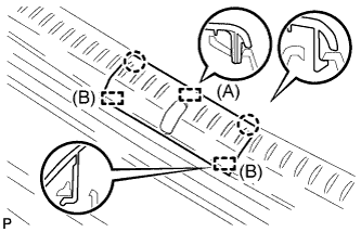 |
Engage the 2 guides (B).
Engage the 2 claws and guide (A) to install the deck trim service hole cover.
| 59. INSTALL REAR NO. 1 FLOOR BOARD |
Engage the 2 claws and 2 clips.
Install the rear No. 1 floor board with the bolt.
| 60. INSTALL REAR NO. 2 FLOOR BOARD SUB-ASSEMBLY |
Engage the claw and 2 clips to install the rear No. 2 floor board sub-assembly.
| 61. INSTALL REAR NO. 1 FLOOR BOARD SUB-ASSEMBLY |
Engage the 2 claws and 2 clips to install the rear No. 1 floor board sub-assembly.
| 62. INSTALL TONNEAU COVER ASSEMBLY (w/ Tonneau Cover) |
Install the tonneau cover assembly.
| 63. INSTALL DECK FLOOR BOX LH (w/o Woofer) |
Engage the 6 guides.
Install the deck floor box LH with the clip.
| 64. INSTALL REAR NO. 4 FLOOR BOARD (w/o Woofer) |
Install the rear No. 4 floor board.
| 65. INSTALL REAR NO. 4 FLOOR BOARD (w/ Woofer) |
Engage the 2 clips and 3 guides to install the rear No. 4 floor board.
| 66. INSTALL REAR SEATBACK ASSEMBLY RH |
Place the rear seatback assembly RH in the cabin.
Install the rear seatback assembly RH with the 2 bolts.
Engage the fastener to connect the rear No. 1 floor board sub-assembly.
| 67. INSTALL REAR SEATBACK ASSEMBLY LH |
Place the rear seatback assembly LH in the cabin.
Install the rear seatback assembly LH with the 2 bolts.
Engage the fastener to connect the rear No. 2 floor board sub-assembly.
| 68. INSTALL REAR SEAT CUSHION LOCK HOOK |
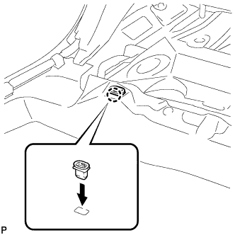 |
Engage the claw to install a new rear seat cushion lock hook.
| 69. INSTALL REAR SEAT CUSHION ASSEMBLY |
Place the rear seat cushion assembly in the cabin.
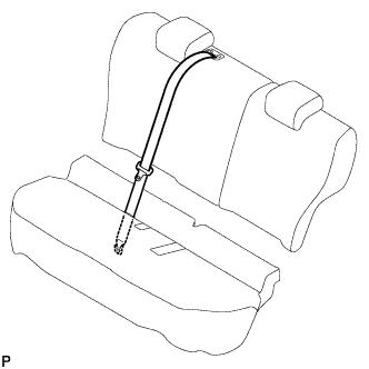 |
Pass the rear center seat outer belt assembly through the rear seat cushion assembly.
Install the rear center seat outer belt assembly with the bolt.
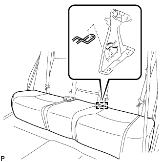 |
Engage the guide as shown in the illustration.
Pass the rear seat inner with center belt assembly LH and rear seat inner belt assembly through the rear seat cushion assembly as shown in the illustration.
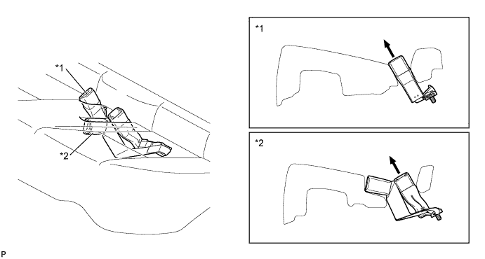
| *1 | Rear Seat Inner Belt Assembly | *2 | Rear Seat Inner with Center Belt Assembly LH |
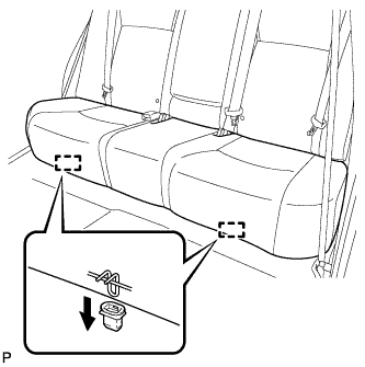 |
Engage the 2 hooks of the seat cushion to the vehicle body as shown in the illustration.
Confirm that the seat cushion is firmly installed.
| 70. INSTALL REAR FLOOR BOARD UPPER NO. 3 PLATE |
Engage the 4 claws and 2 guides to install the rear floor board upper No. 3 plate.
| 71. INSTALL DECK FLOOR BOX RH |
Engage the 6 guides.
Install the deck floor box RH with the clip.
| 72. INSTALL REAR NO. 3 FLOOR BOARD |
Install the rear No. 3 floor board.
| 73. INSTALL REAR DECK FLOOR BOX |
Install the rear deck floor box.
| 74. INSTALL REAR NO. 2 FLOOR BOARD |
Install the rear No. 2 floor board.
