REAR WHEEL ALIGNMENT > ADJUSTMENT |
| 1. INSPECT TIRES |
Check the tires for wear and proper inflation pressure.
| Area | Tire Size | For driving under 160 km/h (100 mph) | For driving at over 160 km/h (100 mph) | ||
| Front kPa (kgf/cm2, psi) | Rear kPa (kgf/cm2, psi) | Front kPa (kgf/cm2, psi) | Rear kPa (kgf/cm2, psi) | ||
| Europe (Countries that use WVTA) | 195/65R15 91H | 230 (2.3, 33)*1 270 (2.7 ,39)*2 | 250 (2.5, 36) | ||
| 205/55R16 91V | 220 (2.2, 32) | 240 (2.4, 35) | |||
| 215/45R17 87W | 230 (2.3, 33) | 220 (2.2, 32) | 230 (2.3, 33) | 220 (2.2, 32) | |
| Europe (Countries that do not use WVTA) | 195/65R15 91H | 230 (2.3, 33) | 250 (2.5, 36) | ||
| 205/55R16 91V | 220 (2.2, 32) | 240 (2.4, 35) | |||
| 215/45R17 87W | 230 (2.3, 33) | 220 (2.2, 32) | 230 (2.3, 33) | 220 (2.2, 32) | |
| GCC | 205/55R16 91V | 220 (2.2, 32) | 240 (2.4, 35) | ||
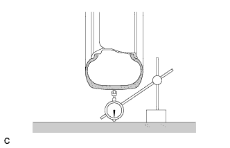 |
Using a dial indicator, check the runout of the tires.
| 2. MEASURE VEHICLE HEIGHT |
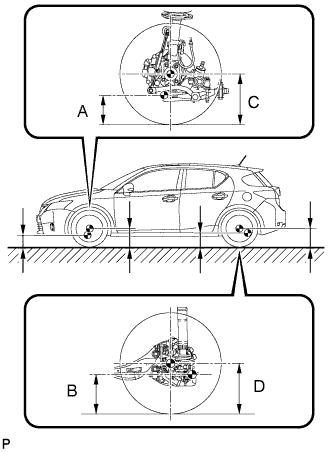 |
Bounce the vehicle up and down at the corners to stabilize the suspension.
Measure the vehicle height.
| Tire Size | Front C - A | Rear D - B |
| 195/65R15 | 112 mm (4.41 in.) | 61 mm (2.40 in.) |
| 205/55R16 215/45R17 (except sport) | 104 mm (4.09 in.) | 64 mm (2.52 in.) |
| 205/55R16 215/45R17 (sport) | 106 mm (4.17 in.) | 59 mm (2.32 in.) |
| 3. INSPECT CAMBER |
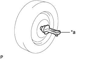 |
Install a camber-caster-kingpin gauge.
| *a | Camber-caster-kingpin Gauge |
Inspect the camber.
| Camber Inclination | Right-left Difference |
| -1°00' +/- 0°45' (-1.00° +/- 0.75°) | 0°45' (0.75°) or less |
| 4. INSPECT TOE-IN |
Bounce the vehicle up and down at the corners to stabilize the suspension.
Release the parking brake and move the shift lever to N.
Push the vehicle straight ahead approximately 5 m (16.4 ft.). (Step A)
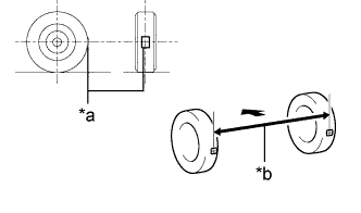 |
Put tread center marks on the rearmost points of the rear wheels and measure the distance between the marks (dimension B).
| *a | Tread Center Mark |
| *b | Dimension B |
 | Front of the Vehicle |
Slowly push the vehicle straight ahead to cause the rear wheels to rotate 180° using the rear tire valve as a reference point.
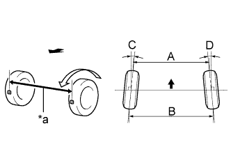 |
Measure the distance between the tread center marks on the front side of the rear wheels (dimension A).
| *a | Dimension A |
| Front of the Vehicle |
| Specified Condition | Right-left Difference |
| C + D: 0°12' +/- 0°12' ( 0.20° +/- 0.20°) | 0°06' (0.10°) or less |
| B - A: 2.0 +/- 2.0 mm (0.0787 +/- 0.0787 in.) | 1.0 mm (0.0393 in.) or less |
| 5. ADJUST TOE-IN |
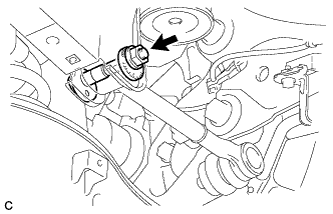 |
Loosen the nut of the rear No. 1 suspension arm assembly (at the rear suspension member side).
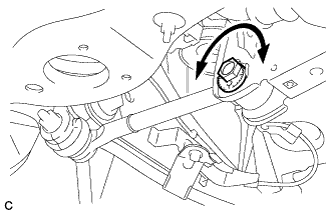 |
Rotate the rear suspension toe adjust cam sub-assembly to adjust the toe-in.
| Specified Condition | Right-left Difference |
| C + D: 0°12' +/- 0°12' ( 0.20° +/- 0.20°) | 0°06' (0.10°) or less |
| B - A: 2.0 +/- 2.0 mm (0.0787 +/- 0.0787 in.) | 1.0 mm (0.0393 in.) or less |
|
Tighten the nut of the rear No. 1 suspension arm assembly (at the rear suspension member side).
| 6. PLACE FRONT WHEELS FACING STRAIGHT AHEAD |
| 7. PERFORM YAW RATE AND ACCELERATION SENSOR CALIBRATION |
| 8. PERFORM INITIALIZATION (w/ Height Control Sensor) |
