PARKING BRAKE PEDAL (for LHD) > INSTALLATION |
| 1. INSTALL PARKING BRAKE CONTROL PEDAL ASSEMBLY |
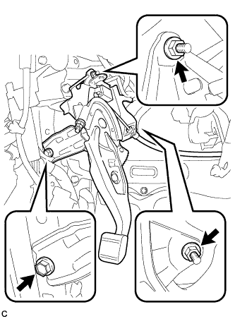 |
Install the parking brake control pedal assembly with the bolt and 2 nuts.
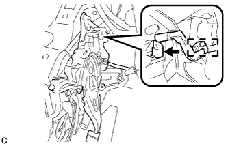 |
Connect the parking brake switch connector.
Engage the wire harness clamp.
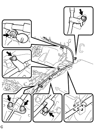 |
Install the No. 1 parking brake cable assembly with the 5 bolts and nut.
Engage the cable with the clamp.
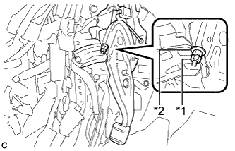 |
Temporarily install the lock nut.
| *1 | Lock Nut |
| *2 | Adjusting Nut |
| 2. CONNECT NO. 1 PARKING BRAKE PULL ROD SUB-ASSEMBLY |
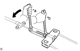 |
Connect the No. 1 parking brake pull rod sub-assembly to the parking brake control pedal assembly as shown in the illustration.
| *a | Turn |
| *b | Hold |
| 3. INSTALL FRONT FLOOR CENTER REINFORCEMENT |
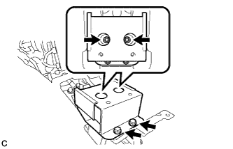 |
Install the front floor center reinforcement with the 4 bolts.
| 4. INSTALL YAW RATE AND ACCELERATION SENSOR |
Connect the yaw rate and acceleration sensor connector.
Install the yaw rate and acceleration sensor with the 2 bolts.
| 5. INSTALL NO. 2 CONSOLE BOX MOUNTING BRACKET |
Install the No. 2 console box mounting bracket with the 2 bolts.
Engage the clamp.
| 6. INSTALL MULTI-MEDIA INTERFACE ECU ASSEMBLY (w/ Audio) |
Connect each connector.
Engage the guide and install the multi-media interface ECU assembly with the bolt.
| 7. INSTALL NO. 1 ELECTRICAL KEY OSCILLATOR |
Engage the clamp and install the No. 1 electrical key oscillator.
Connect the connector.
| 8. INSTALL MULTI-MEDIA MODULE ASSEMBLY (w/ Navigation System for DVD) |
Install the multi-media module assembly with the 4 bolts.
Connect the 2 connectors.
| 9. INSTALL AIR CONDITIONING UNIT ASSEMBLY |
| 10. ADJUST PARKING BRAKE PEDAL TRAVEL |
Remove the lower instrument panel finish panel sub-assembly (Click here).
Completely release the parking brake pedal.
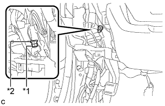 |
Loosen the lock nut and the adjusting nut to completely release the parking brake cable.
| *1 | Lock Nut |
| *2 | Adjusting Nut |
Turn the adjusting nut until the parking brake pedal travel is corrected to be within the specified range.
Using a wrench or an equivalent tool, hold the adjusting nut and tighten the lock nut.
Operate the parking brake pedal 3 to 4 times, and check the parking brake pedal travel.
Check that the parking brake does not drag.
Install the lower instrument panel finish panel sub-assembly (Click here).
| 11. INSPECT BRAKE WARNING LIGHT |
When operating the parking brake pedal, check that the brake warning light illuminates.
