PARKING BRAKE PEDAL (for RHD) > REMOVAL |
| 1. REMOVE DRIVER SIDE KNEE AIRBAG ASSEMBLY |
| 2. REMOVE REAR CONSOLE BOX ASSEMBLY |
| 3. REMOVE SHIFT LEVER KNOB SUB-ASSEMBLY |
| 4. REMOVE INTEGRATION CONTROL AND PANEL ASSEMBLY |
| 5. REMOVE CONSOLE BOX INSERT |
| 6. REMOVE CONSOLE BOX RH |
| 7. REMOVE FRONT NO. 2 CONSOLE BOX INSERT |
| 8. REMOVE CONSOLE BOX LH |
| 9. REMOVE NO. 3 CONSOLE BOX MOUNTING BRACKET |
| 10. REMOVE NO. 1 CONSOLE BOX MOUNTING BRACKET |
| 11. REMOVE MULTI-MEDIA MODULE ASSEMBLY (w/ Navigation System for DVD) |
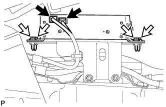 |
Disconnect the 2 connectors.
Remove the 4 bolts and multi-media module assembly.
| 12. REMOVE NO. 1 ELECTRICAL KEY OSCILLATOR |
| 13. REMOVE MULTI-MEDIA INTERFACE ECU ASSEMBLY (w/ Audio) |
| 14. REMOVE NO. 2 CONSOLE BOX MOUNTING BRACKET |
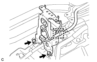 |
Disengage the clamp.
Remove the 2 bolts and No. 2 console box mounting bracket.
| 15. REMOVE YAW RATE AND ACCELERATION SENSOR |
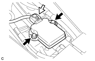 |
Remove the 2 bolts and yaw rate and acceleration sensor.
Disconnect the connector from the yaw rate and acceleration sensor.
| 16. REMOVE FRONT FLOOR CENTER REINFORCEMENT |
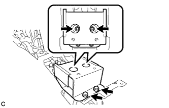 |
Remove the 4 bolts and front floor center reinforcement.
| 17. REMOVE NO. 2 AIR DUCT SUB-ASSEMBLY |
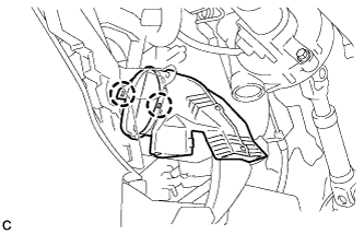 |
Disengage the 2 claws to remove the No. 2 air duct sub-assembly.
| 18. LOOSEN ADJUSTING NUT |
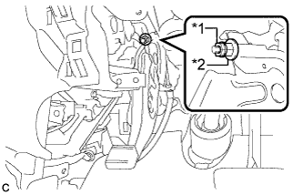 |
Remove the lock nut and loosen the adjusting nut.
| *1 | Lock Nut |
| *2 | Adjusting Nut |
| 19. SEPARATE NO. 1 PARKING BRAKE PULL ROD SUB-ASSEMBLY |
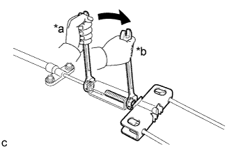 |
Separate the No. 1 parking brake pull rod sub-assembly from the parking brake control pedal assembly as shown in the illustration.
| *a | Turn |
| *b | Hold |
| 20. REMOVE PARKING BRAKE CONTROL PEDAL ASSEMBLY |
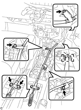 |
Remove the 5 bolts and separate the No. 1 parking brake cable assembly.
Disengage the cable from the clamp.
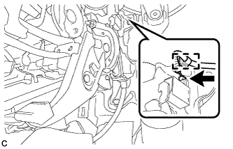 |
Disconnect the parking brake switch connector.
Disengage the wire harness clamp.
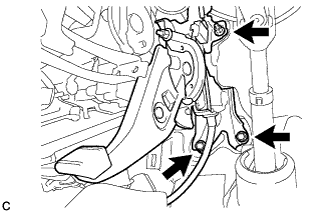 |
Remove the 2 bolts, nut and parking brake control pedal assembly.
