FUEL PUMP > INSTALLATION |
| 1. INSTALL FUEL SUCTION TUBE ASSEMBLY WITH PUMP AND GAUGE |
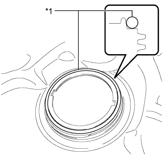 |
Install a new gasket onto the fuel tank.
| *1 | Gasket |
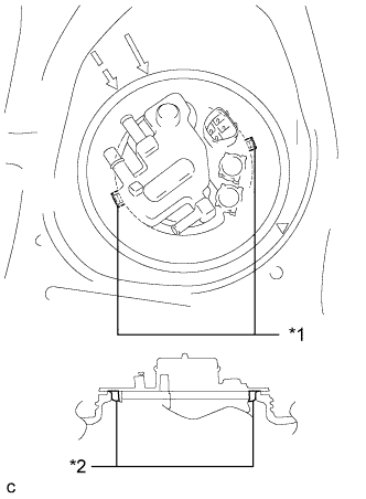 |
Set the fuel suction tube assembly with pump and gauge to the fuel tank.
| *1 | Notch |
| *2 | Protrusion |
Align the protrusions of the fuel suction tube assembly with pump and gauge with the notches of the fuel tank.
| 2. INSTALL FUEL PUMP GAUGE RETAINER |
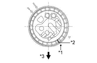 |
While holding the fuel suction tube assembly with pump and gauge by hand to prevent it from tilting, align the mark on the new fuel pump gauge retainer with the start mark on the fuel tank and tighten the fuel pump gauge retainer 180° by hand.
| *1 | Start Mark |
| *2 | Mark |
| *3 | Front |
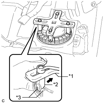 |
Temporarily install the SST plate and claws to the fuel pump gauge retainer.
| *1 | SST (Plate) |
| *2 | SST (Claw) |
| *3 | Rib |
While pressing the claws of SST to the fuel pump gauge retainer ribs securely, tighten the bolts.
Install the SST handle.
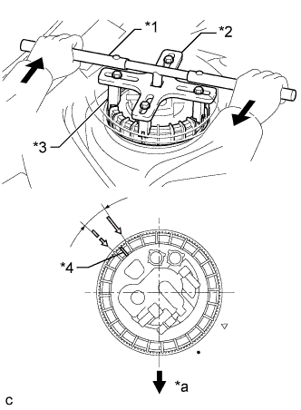 |
Tighten the fuel pump gauge retainer approximately 360° so that the mark on the retainer comes within the range shown in the illustration.
| *1 | SST (Handle) |
| *2 | SST (Plate) |
| *3 | SST (Claw) |
| *4 | Mark |
| *a | Front Side |
| 3. CONNECT FUEL TANK EVAPORATION TUBE |
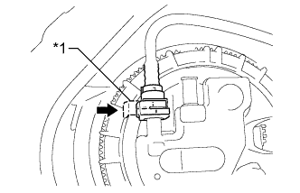 |
Connect the fuel tank evaporation tube to the fuel suction tube assembly.
| *1 | Retainer |
| 4. CONNECT NO. 1 CHARCOAL CANISTER OUTLET HOSE |
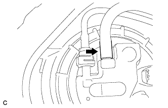 |
Connect the No. 1 charcoal canister outlet hose to the fuel suction tube assembly.
| 5. CONNECT NO. 1 FUEL EVAPORATION TUBE SUB-ASSEMBLY |
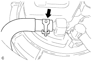 |
Connect the No. 1 fuel evaporation tube sub-assembly to the fuel suction tube assembly with the clip.
| 6. CONNECT FUEL TANK MAIN TUBE SUB-ASSEMBLY |
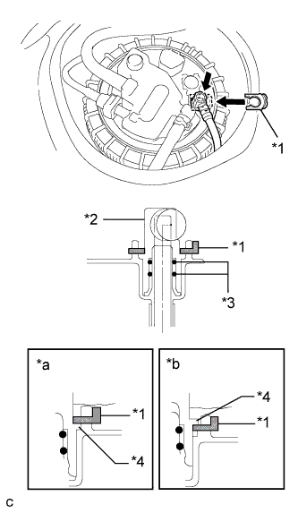 |
Push the fuel tube joint in the plug of the fuel suction plate, then install the tube joint clip.
| *1 | Tube Joint Clip |
| *2 | Fuel Tube Joint |
| *3 | O-ring |
| *4 | Collar |
| *a | CORRECT |
| *b | INCORRECT |
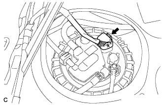 |
Connect the fuel pump connector.
| 7. CONNECT CABLE TO NEGATIVE AUXILIARY BATTERY TERMINAL |
| 8. INSPECT FOR FUEL LEAK |
Check fuel pump operation.
Connect the intelligent tester to the DLC3.
Turn the power switch on (IG).
Turn the intelligent tester on.
Enter the following menus: Powertrain / Engine and ECT / Active Test / Control the Fuel Pump / Speed.
Check for pressure in the fuel inlet tube from the fuel line. Check that sounds of fuel flowing from the fuel tank can be heard. If no sounds can be heard, check the integration relay, fuel pump, ECM and wiring connectors.
Inspect for fuel leaks.
Check that there are no fuel leaks after performing maintenance anywhere on the fuel system. If there are fuel leaks, repair or replace parts as necessary.
Turn the power switch off.
Disconnect the intelligent tester from the DLC3.
| 9. INSTALL REAR FLOOR SERVICE HOLE COVER |
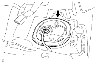 |
Install the rear floor service hole cover with new butyl tape.
| 10. INSTALL REAR SEAT CUSHION LOCK HOOK |
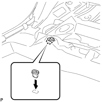 |
Engage the claw to install a new rear seat cushion lock hook.
| 11. INSTALL REAR SEAT CUSHION ASSEMBLY |
Place the rear seat cushion assembly in the cabin.
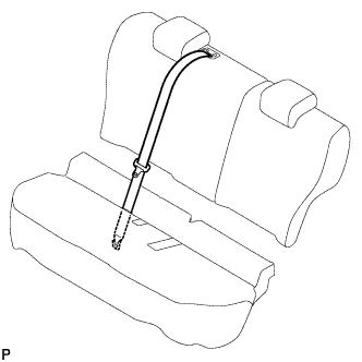 |
Pass the rear center seat outer belt assembly through the rear seat cushion assembly.
Install the rear center seat outer belt assembly with the bolt.
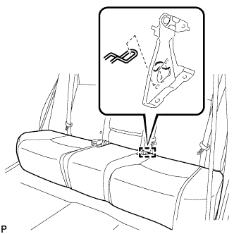 |
Engage the guide as shown in the illustration.
Pass the rear seat inner with center belt assembly LH and rear seat inner belt assembly through the rear seat cushion assembly as shown in the illustration.
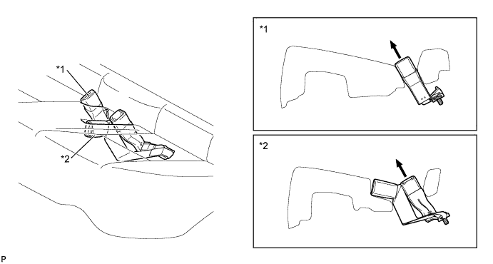
| *1 | Rear Seat Inner Belt Assembly | *2 | Rear Seat Inner with Center Belt Assembly LH |
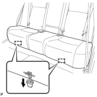 |
Engage the 2 hooks of the seat cushion to the vehicle body as shown in the illustration.
Confirm that the seat cushion is firmly installed.
| 12. INSTALL REAR FLOOR BOARD UPPER NO. 3 PLATE |
Engage the 4 claws and 2 guides to install the rear floor board upper No. 3 plate.
| 13. INSTALL DECK FLOOR BOX RH |
Engage the 6 guides.
Install the deck floor box RH with the clip.
| 14. INSTALL REAR NO. 3 FLOOR BOARD |
Install the rear No. 3 floor board.
| 15. INSTALL REAR DECK FLOOR BOX |
Install the rear deck floor box.
| 16. INSTALL REAR NO. 2 FLOOR BOARD |
Install the rear No. 2 floor board.
