FUEL PUMP > REMOVAL |
| 1. PRECAUTION |
| 2. DISCHARGE FUEL SYSTEM PRESSURE |
| 3. REMOVE REAR NO. 2 FLOOR BOARD |
Remove the rear No. 2 floor board.
| 4. REMOVE REAR DECK FLOOR BOX |
Remove the rear deck floor box.
| 5. REMOVE REAR NO. 3 FLOOR BOARD |
Remove the rear No. 3 floor board.
| 6. REMOVE DECK FLOOR BOX RH |
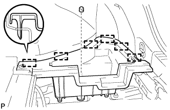 |
Remove the clip.
Disengage the 6 guides and remove the deck floor box RH.
| 7. REMOVE REAR FLOOR BOARD UPPER NO. 3 PLATE |
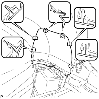 |
Disengage the 4 claws and 2 guides, and remove the rear floor board upper No. 3 plate.
| 8. DISCONNECT CABLE FROM NEGATIVE AUXILIARY BATTERY TERMINAL |
| 9. REMOVE REAR SEAT CUSHION ASSEMBLY |
Disengage the hook of the seat cushion from the vehicle body as shown in the illustration.
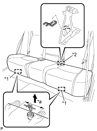 |
Choose a hook to disengage first. Place your hands near the hook as shown in the illustration. Then lift the seat cushion to disengage the hook.
| *1 | Hook |
| *2 | Guide |
| *a | 100 mm (3.94 in.) or less |
Repeat the step above for the other hook.
Disengage the guide of the seat cushion from the seatback.
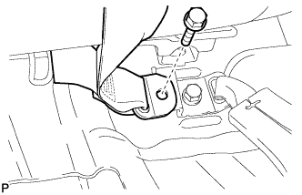 |
Remove the bolt and disconnect the rear center seat outer belt assembly.
Pull out the rear center seat outer belt assembly from the rear seat cushion assembly.
Remove the rear seat cushion assembly.
| 10. REMOVE REAR SEAT CUSHION LOCK HOOK |
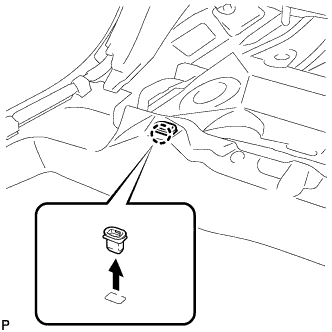 |
Disengage the claw and remove the rear seat cushion lock hook.
| 11. REMOVE REAR FLOOR SERVICE HOLE COVER |
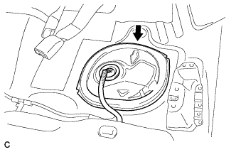 |
Remove the rear floor service hole cover.
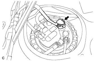 |
Disconnect the connector from the fuel suction tube assembly.
| 12. DISCONNECT FUEL TANK MAIN TUBE SUB-ASSEMBLY |
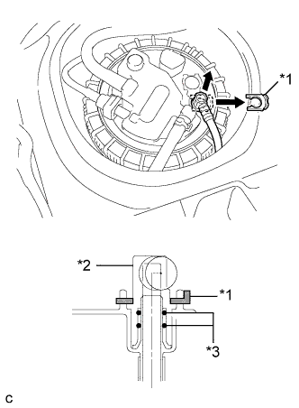 |
Remove the tube joint clip, then pull the fuel tube joint out of the plug of the fuel suction tube assembly.
| *1 | Tube Joint Clip |
| *2 | Fuel Tube Joint |
| *3 | O-ring |
| 13. DISCONNECT NO. 1 FUEL EVAPORATION TUBE SUB-ASSEMBLY |
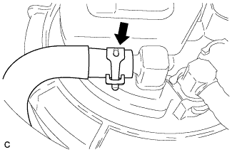 |
Loosen the clip and disconnect the No. 1 fuel evaporation tube sub-assembly from the fuel suction tube assembly.
| 14. DISCONNECT NO. 1 CHARCOAL CANISTER OUTLET HOSE |
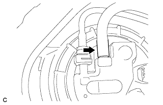 |
Disconnect the No. 1 charcoal canister outlet hose from the fuel suction tube assembly.
| 15. DISCONNECT FUEL TANK EVAPORATION TUBE |
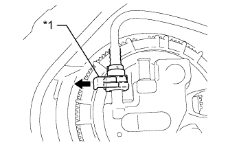 |
Release the retainer and disconnect the fuel tank evaporation tube from the fuel suction tube assembly.
| *1 | Retainer |
| 16. REMOVE FUEL PUMP GAUGE RETAINER |
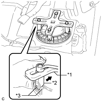 |
Temporarily install the SST plate and claws to the fuel pump gauge retainer.
| *1 | SST (Plate) |
| *2 | SST (Claw) |
| *3 | Rib |
While pressing the claws of SST to the fuel pump gauge retainer ribs securely, tighten the bolts.
Install the SST handle.
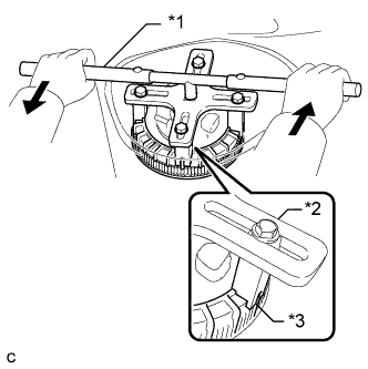 |
Lightly press down on SST to prevent it from separating from the retainer. While pressing SST, rotate the handle slowly to loosen the retainer.
| *1 | SST (Handle) |
| *2 | SST (Plate) |
| *3 | SST (Claw) |
Remove the fuel pump gauge retainer while holding the fuel suction tube assembly by hand.
| 17. REMOVE FUEL SUCTION TUBE ASSEMBLY WITH PUMP AND GAUGE |
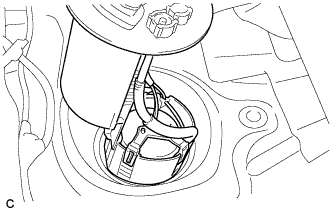 |
Remove the fuel suction tube assembly with pump and gauge from the fuel tank.
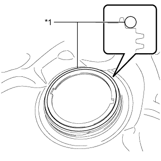 |
Remove the gasket from the fuel tank.
| *1 | Gasket |
