DTC P0A82-123 Hybrid Battery Pack Cooling Fan 1 |
| DTC No. | DTC Detection Condition | Trouble Area |
| P0A82-123 | The speed of the battery cooling blower assembly is not within the specified range (1 trip detection) |
|
| 1.CHECK DTC OUTPUT (HV) |
Connect the intelligent tester to the DLC3.
Turn the power switch on (IG).
Enter the following menus: Powertrain / Hybrid Control / DTC.
Check if DTCs are output.
| Result | Proceed to |
| P0AFC-123 is not output. | A |
| P0AFC-123 is also output. | B |
Turn the power switch off.
|
| ||||
| A | |
 |
| 2.CHECK DUCT AND BLOWER |
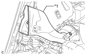 |
Check that the No. 1 hybrid battery intake duct and battery cooling blower are not disconnected, damaged, or clogged with foreign objects, and that the acoustical materials have not peeled.
| *1 | No. 1 Hybrid Battery Intake Duct |
|
| ||||
| OK | |
|
| 3.CHECK HARNESS AND CONNECTOR (BATTERY COOLING BLOWER - POWER MANAGEMENT CONTROL ECU) |
Disconnect the cable from the negative (-) auxiliary battery terminal.
Check that the service plug grip is not installed.
Disconnect connector A19 from the power management control ECU (Click here).
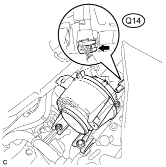 |
Disconnect connector Q14 from the battery cooling blower assembly.
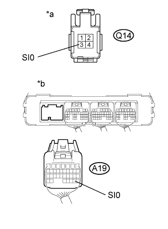 |
Measure the resistance according to the value(s) in the table below.
| Tester Connection | Specified Condition |
| Q14-3 (SI0) or A19-29 (SI0) - Body ground | 10 kΩ or higher |
| Q14-3 (SI0) - A19-29 (SI0) | Below 1 Ω |
| *a | Front view of wire harness connector (to Battery Cooling Blower Assembly) |
| *b | Rear view of wire harness connector (Power Management Control ECU) |
Connect the battery cooling blower assembly connector.
Connect the power management control ECU connector (Click here).
Connect the cable to the negative (-) auxiliary battery terminal.
|
| ||||
| OK | |
|
| 4.CHECK POWER MANAGEMENT CONTROL ECU (GROUND SHORT CHECK) |
Remove the power management control ECU (Click here).
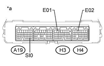 |
Measure the resistance according to the value(s) in the table below.
| Tester Connection | Specified Condition |
| A19-29 (SI0) - H3-5 (E01) | 10 kΩ or higher |
| A19-29 (SI0) - H4-5 (E02) | 10 kΩ or higher |
| *a | Component without harness connected (to Power Management Control ECU) |
Install the power management control ECU (Click here).
|
| ||||
| OK | |
|
| 5.READ VALUE USING INTELLIGENT TESTER |
Check that the service plug grip is not installed.
Connect the intelligent tester to the DLC3.
Turn the power switch on (IG).
Enter the following menus: Powertrain / Hybrid Control / Active Test / Driving the Battery Cooling Fan.
Enter the following menus: All Data / VMF Fan Motor Voltage 1.
Select each air volume mode (1 to 6) in the "Driving the Battery Cooling Fan" Active Test to operate the battery cooling blower assembly.
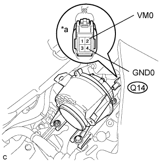 |
While the cooling fan is operating, compare the value in the data list (VMF Fan Motor Voltage 1) with the voltage value that was actually measured at the battery cooling blower assembly connector.
| Tester Connection | Condition | Specified Condition |
| Q14-2 (VM0) - Q14-4 (GND0) | Battery cooling blower is operating. | Difference between the value in the Data List (VMF Fan Motor Voltage 1) and the actual measurement value is 1 V or less. |
| *a | Component with harness connected (Battery Cooling Blower Assembly) |
|
| ||||
| OK | ||
 | ||
| ||

