DTC P0ABF-123 Hybrid Battery Pack Current Sensor Circuit |
DTC P0AC1-123 Hybrid Battery Pack Current Sensor "A" Circuit Low |
DTC P0AC2-123 Hybrid Battery Pack Current Sensor "A" Circuit High |
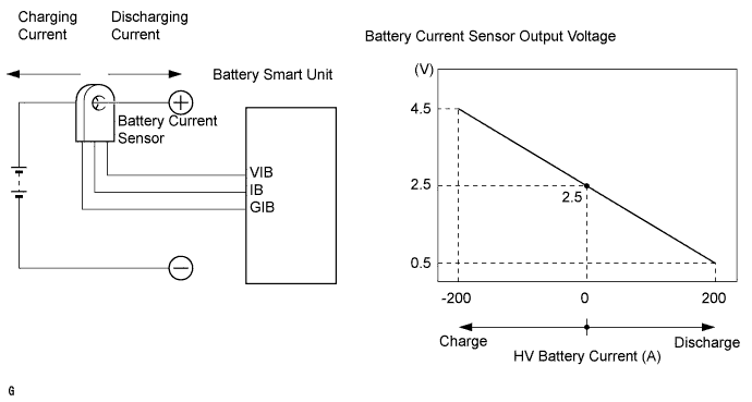
| DTC No. | DTC Detection Condition | Trouble Area |
| P0ABF-123 P0AC1-123 P0AC2-123 | When the battery current sensor is abnormal (1 trip detection) |
|
| 1.CHECK DTC OUTPUT (HV) |
Connect the intelligent tester to the DLC3.
Turn the power switch on (IG).
Enter the following menus: Powertrain / Hybrid Control / DTC.
Check if DTCs are output.
| Result | Proceed to |
| P0AFC-123 is not output. | A |
| P0AFC-123 is also output. | B |
Turn the power switch off.
|
| ||||
| A | |
 |
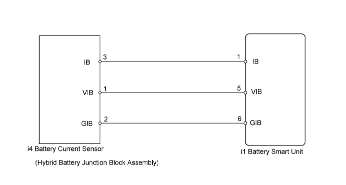
| 2.CHECK HARNESS AND CONNECTOR (HYBRID BATTERY JUNCTION BLOCK ASSEMBLY - BATTERY SMART UNIT) |
Check that the service plug grip is not installed.
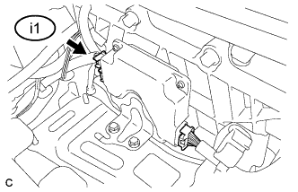 |
Disconnect connector i1 from the battery smart unit.
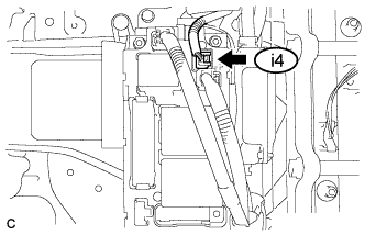 |
Disconnect connector i4 from the hybrid battery junction block assembly.
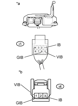 |
Measure the resistance according to the value(s) in the tables below.
| Tester Connection | Switch Condition | Specified Condition |
| i1-1 (IB) - i4-3 (IB) | Power switch off | Below 1 Ω |
| i1-6 (GIB) - i4-2 (GIB) | Power switch off | Below 1 Ω |
| i1-5 (VIB) - i4-1 (VIB) | Power switch off | Below 1 Ω |
| Tester Connection | Switch Condition | Specified Condition |
| i1-1 (IB) or i4-3 (IB) - Body ground and other terminals | Power switch off | 10 kΩ or higher |
| i1-6 (GIB) or i4-2 (GIB) - Body ground and other terminals | Power switch off | 10 kΩ or higher |
| i1-5 (VIB) or i4-1 (VIB) - Body ground and other terminals | Power switch off | 10 kΩ or higher |
| *a | Rear view of wire harness connector (to Battery Smart Unit) |
| *b | Front view of wire harness connector (to Hybrid Battery Junction Block Assembly) |
Connect the battery smart unit connector.
Connect the hybrid battery junction block assembly connector.
|
| ||||
| OK | |
|
| 3.CHECK BATTERY SMART UNIT (VIB VOLTAGE) |
Check that the service plug grip is not installed.
Turn the power switch on (IG).
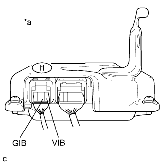 |
Measure the voltage according to the value(s) in the table below.
| Tester Connection | Switch Condition | Specified Condition |
| i1-5 (VIB) - i1-6 (GIB) | Power switch on (IG) | 4.6 to 5.4 V |
| *a | Component with harness connected (Battery Smart Unit) |
Turn the power switch off.
|
| ||||
| OK | |
|
| 4.CHECK BATTERY SMART UNIT |
Check that the service plug grip is not installed.
Turn the power switch on (IG).
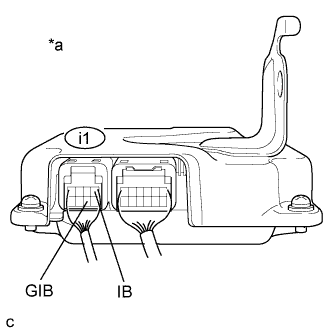 |
Measure the voltage according to the value(s) in the table below.
| Tester Connection | Switch Condition | Specified Condition |
| i1-1 (IB) - i1-6 (GIB) | Power switch on (IG) | 2.46 to 2.54 V |
| *a | Component with harness connected (Battery Smart Unit) |
Turn the power switch off.
|
| ||||
| OK | ||
 | ||
| ||

