DTC P0B3D-123 Hybrid Battery Voltage Sensor "A" Circuit Low |
DTC P0B42-123 Hybrid Battery Voltage Sensor "B" Circuit Low |
DTC P0B47-123 Hybrid Battery Voltage Sensor "C" Circuit Low |
DTC P0B4C-123 Hybrid Battery Voltage Sensor "D" Circuit Low |
DTC P0B51-123 Hybrid Battery Voltage Sensor "E" Circuit Low |
DTC P0B56-123 Hybrid Battery Voltage Sensor "F" Circuit Low |
DTC P0B5B-123 Hybrid Battery Voltage Sensor "G" Circuit Low |
DTC P0B60-123 Hybrid Battery Voltage Sensor "H" Circuit Low |
DTC P0B65-123 Hybrid Battery Voltage Sensor "I" Circuit Low |
DTC P0B6A-123 Hybrid Battery Voltage Sensor "J" Circuit Low |
DTC P0B6F-123 Hybrid Battery Voltage Sensor "K" Circuit Low |
DTC P0B74-123 Hybrid Battery Voltage Sensor "L" Circuit Low |
DTC P0B79-123 Hybrid Battery Voltage Sensor "M" Circuit Low |
DTC P0B7E-123 Hybrid Battery Voltage Sensor "N" Circuit Low |
DTC P0B83-123 Hybrid Battery Voltage Sensor "O" Circuit Low |
DTC P308A-123 Hybrid Battery Voltage Sensor All Circuits Low |
| DTC No. | DTC Detection Condition | Trouble Area |
| P0B3D-123 P0B42-123 P0B47-123 P0B4C-123 P0B51-123 P0B56-123 P0B5B-123 P0B60-123 P0B65-123 P0B6A-123 P0B6F-123 P0B74-123 P0B79-123 P0B7E-123 P0B83-123 P308A-123 | Each battery block voltage becomes less than 2.5 V (open) (1 trip detection) |
|
| 1.CHECK DTC OUTPUT (HV) |
Connect the intelligent tester to the DLC3.
Turn the power switch on (IG).
Enter the following menus: Powertrain / Hybrid Control / DTC.
Check if DTCs are output.
| Result | Proceed to |
| P0AFC-123 is not output. | A |
| P0AFC-123 is also output. | B |
Turn the power switch off.
|
| ||||
| A | |
 |
| 2.CHECK CONNECTOR CONNECTION CONDITION |
Check that the service plug grip is not installed.
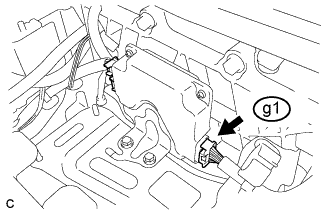 |
Check the connections of the g1 connector of the battery smart unit.
|
| ||||
| OK | |
|
| 3.REPLACE BATTERY SMART UNIT |
Replace the battery smart unit (Click here).
| NEXT | |
|
| 4.CLEAR DTC (HV) |
Connect the intelligent tester to the DLC3.
Turn the power switch on (IG).
Enter the following menus: Powertrain / Hybrid Control / DTC.
Clear the DTCs and freeze frame data (Click here).
Perform a road test to charge and discharge the HV battery.
Disconnect the intelligent tester from the DLC3.
| NEXT | |
|
| 5.RECONFIRM DTC OUTPUT (HV) |
Connect the intelligent tester to the DLC3.
Turn the power switch on (IG).
Enter the following menus: Powertrain / Hybrid Control / DTC.
Read output DTCs (Click here).
| Result | Proceed to |
| Battery temperature sensor DTCs for this diagnostic procedure are not output. | A |
| Battery temperature sensor DTCs for this diagnostic procedure are output. | B |
Disconnect the intelligent tester from the DLC3.
|
| ||||
| A | ||
 | ||
| ||

