DTC P0AAE-123 Hybrid Battery Pack Air Temperature Sensor "A" Circuit Low |
DTC P0AAF-123 Hybrid Battery Pack Air Temperature Sensor "A" Circuit High |
| DTC No. | DTC Detection Condition | Trouble Area |
| P0AAE-123 P0AAF-123 | When the temperature indicated by the inlet air temperature sensor is lower than a predetermined limit (open circuit) or is higher than a predetermined limit (short circuit) |
|
| Displayed Temperature | Malfunction |
| -45°C (-49°F) or less | Open or +B short circuit |
| 95°C (203°F) or more | GND short |
| 1.CHECK DTC OUTPUT (HV) |
Connect the intelligent tester to the DLC3.
Turn the power switch on (IG).
Enter the following menus: Powertrain / Hybrid Control / DTC.
Check if DTCs are output.
| Result | Proceed to |
| P0AFC-123 is not output. | A |
| P0AFC-123 is also output. | B |
Turn the power switch off.
|
| ||||
| A | |
 |
| 2.CHECK INSTALLATION OF INLET AIR TEMPERATURE SENSOR |
Check that the service plug grip is not installed.
Check installation of inlet air temperature sensor
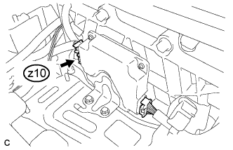 |
Check the connections of connector z10 of the battery smart unit.
| Result | Proceed to |
| NG | B |
| OK | Go to next step |
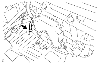 |
Visually check the installation condition of the inlet air temperature sensor.
| Result | Proceed to |
| The inlet air temperature sensor is installed in the correct location and its claws are engaged securely. | A |
| Claws are damaged. | C |
| Inlet air temperature sensor is not installed correctly, but claws are not damaged. | D |
|
| ||||
|
| ||||
|
| ||||
| A | |
|
| 3.CHECK HV BATTERY (INLET AIR TEMPERATURE SENSOR AND BATTERY TEMPERATURE SENSOR) |
Check that the service plug grip is not installed.
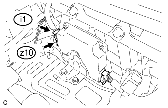 |
Disconnect connectors i1 and z10 from the battery smart unit.
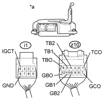 |
Measure the resistance according to the value(s) in the table below.
| Tester Connection | Condition | Specified Condition |
| z10-1 (TCO) - z10-7 (GCO) | 0°C (32°F) | 26.7 to 27.8 kΩ |
| 25°C (77°F) | 9.9 to 10.1 kΩ | |
| 40°C (104°F) | 5.73 to 5.92 kΩ |
| *a | Rear view of wire harness connector (to Battery Smart Unit) |
Measure the resistance according to the value(s) in the table below.
| Tester Connection | Switch Condition | Specified Condition |
| z10-1 (TCO) - i1-4 (IGCT) | Power switch off | 10 kΩ or higher |
| z10-1 (TCO) - i1-8 (GND) | Power switch off | 10 kΩ or higher |
| z10-7 (GCO) - i1-4 (IGCT) | Power switch off | 10 kΩ or higher |
| z10-7 (GCO) - i1-8 (GND) | Power switch off | 10 kΩ or higher |
Measure the resistance according to the value(s) in the table below.
| Tester Connection | Switch Condition | Specified Condition |
| z10-6 (TBO) - i1-4 (IGCT) | Power switch off | 10 kΩ or higher |
| z10-6 (TBO) - i1-8 (GND) | Power switch off | 10 kΩ or higher |
| z10-12 (GBO) - i1-4 (IGCT) | Power switch off | 10 kΩ or higher |
| z10-12 (GBO) - i1-8 (GND) | Power switch off | 10 kΩ or higher |
| z10-5 (TB1) - i1-4 (IGCT) | Power switch off | 10 kΩ or higher |
| z10-5 (TB1) - i1-8 (GND) | Power switch off | 10 kΩ or higher |
| z10-11 (GB1) - i1-4 (IGCT) | Power switch off | 10 kΩ or higher |
| z10-11 (GB1) - i1-8 (GND) | Power switch off | 10 kΩ or higher |
| z10-4 (TB2) - i1-4 (IGCT) | Power switch off | 10 kΩ or higher |
| z10-4 (TB2) - i1-8 (GND) | Power switch off | 10 kΩ or higher |
| z10-10 (GB2) - i1-4 (IGCT) | Power switch off | 10 kΩ or higher |
| z10-10 (GB2) - i1-8 (GND) | Power switch off | 10 kΩ or higher |
Connect the battery smart unit connectors.
|
| ||||
| OK | ||
 | ||
| ||
| 4.CHECK HARNESS AND CONNECTOR (INLET AIR TEMPERATURE SENSOR AND BATTERY TEMPERATURE SENSOR) |
Check that the service plug grip is not installed.
Check the wire harness and connectors of the battery temperature sensor and inlet air temperature sensor for abnormalities by sight and touch.
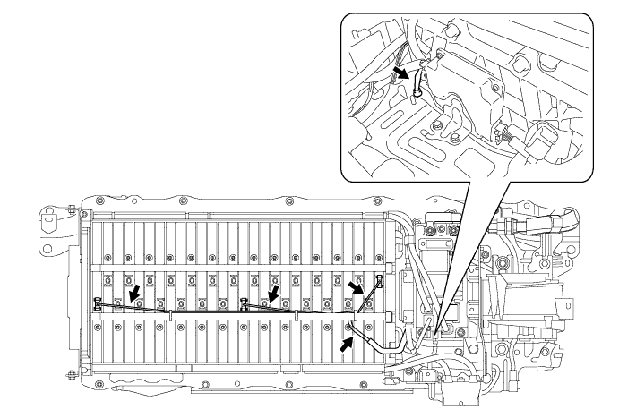
|
| ||||
| OK | ||
| ||
| ||


