DTC P2120-152 Throttle / Pedal Position Sensor / Switch "D" Circuit |
DTC P2121-106 Throttle / Pedal Position Sensor / Switch "D" Circuit Range / Performance |
DTC P2122-104 Throttle / Pedal Position Sensor / Switch "D" Circuit Low Input |
DTC P2123-105 Throttle / Pedal Position Sensor / Switch "D" Circuit High Input |
DTC P2125-153 Throttle / Pedal Position Sensor / Switch "E" Circuit |
DTC P2126-109 Throttle / Pedal Position Sensor / Switch "E" Circuit Range / Performance |
DTC P2127-107 Throttle / Pedal Position Sensor / Switch "E" Circuit Low Input |
DTC P2128-108 Throttle / Pedal Position Sensor / Switch "E" Circuit High Input |
DTC P2138-110 Throttle / Pedal Position Sensor / Switch "D" / "E" Voltage Correlation |
DTC P2138-154 Throttle / Pedal Position Sensor / Switch "D" / "E" Voltage Correlation |
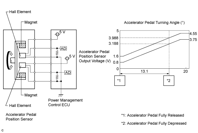
| DTC No. | INF Code | DTC Detection Condition | Trouble Area |
| P2120 | 152 | Main sensor circuit wiring malfunction or level is not stable |
|
| P2121 | 106 | Internal error of the main sensor | |
| P2122 | 104 | Open or short to GND in the main sensor circuit | |
| P2123 | 105 | Short to +B in the main sensor circuit | |
| P2125 | 153 | Sub sensor circuit wiring malfunction or level is not stable | |
| P2126 | 109 | Internal error of the sub sensor | |
| P2127 | 107 | Open or short to GND in the sub sensor circuit | |
| P2128 | 108 | Short to +B in the sub sensor circuit | |
| P2138 | 110 | Difference between the main sensor value and sub sensor value is large. | |
| P2138 | 154 | Main or sub sensor circuit wiring malfunction |
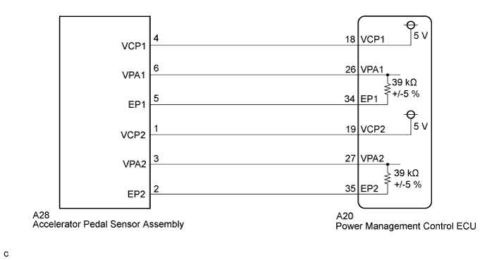
| 1.PERFORM ACTIVE TEST USING INTELLIGENT TESTER (ACCEL PEDAL POS #1, ACCEL PEDAL POS #2) |
Connect the intelligent tester to the DLC3.
Turn the power switch on (IG).
Enter the following menus: Powertrain / Hybrid Control / Data List / Accel Pedal Pos #1, Accel Pedal Pos #2.
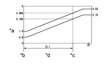 |
Read the Data List.
| Tester Display | Accelerator Pedal Condition | Specified Condition |
| Accel Pedal Pos #1 | Not depressed | 8 to 28% (0.4 to 1.4 V) |
| Fully depressed | 62 to 92% (3.1 to 4.6 V) | |
| Not depressed → Fully depressed → Not depressed (Accelerator pedal should be operated slowly) | Value changes progressively as shown in the illustration | |
| Accel Pedal Pos #2 | Not depressed | 20 to 44% (1.0 to 2.2 V) |
| Fully depressed | 78 to 100% (3.9 to 5.0 V) | |
| Not depressed → Fully depressed → Not depressed (Accelerator pedal should be operated slowly) | Value changes progressively as shown in the illustration |
| *a | Accelerator Pedal Position Sensor Output Voltage (V) |
| *b | Accelerator Pedal Fully Released |
| *c | Accelerator Pedal Fully depressed |
| *d | Accelerator Pedal Turning Angle (°) |
Turn the power switch off.
|
| ||||
| OK | ||
 | ||
| ||
| 2.CHECK CONNECTOR CONNECTION CONDITION (ACCELERATOR PEDAL SENSOR ASSEMBLY CONNECTOR) |
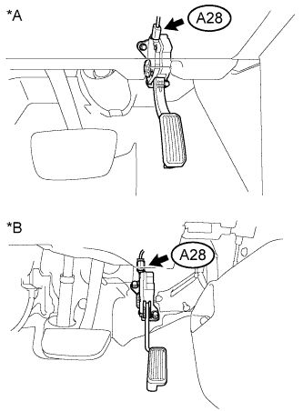 |
Check the connection of the accelerator pedal sensor assembly connector A28.
| *A | for LHD |
| *B | for RHD |
|
| ||||
| OK | |
 |
| 3.CHECK CONNECTOR CONNECTION CONDITION (POWER MANAGEMENT CONTROL ECU CONNECTOR) |
Check the connections of the power management control ECU connectors.
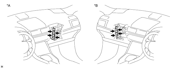
| *A | for LHD | *B | for RHD |
|
| ||||
| OK | |
|
| 4.CHECK POWER MANAGEMENT CONTROL ECU (CHECK VOLTAGE) |
Disconnect connector A28 from the accelerator pedal sensor assembly.
Turn the power switch on (IG).
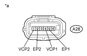 |
Measure the voltage according to the value(s) in the table below.
| Tester Connection | Switch Condition | Specified Condition |
| A28-4 (VCP1) - A28-5 (EP1) | Power switch on (IG) | 4.5 to 5.5 V |
| A28-1 (VCP2) - A28-2 (EP2) | Power switch on (IG) | 4.5 to 5.5 V |
| *a | Front view of wire harness connector (to Accelerator Pedal Sensor Assembly) |
Connect the accelerator pedal sensor assembly connector.
Turn the power switch off.
|
| ||||
| OK | |
|
| 5.CHECK POWER MANAGEMENT CONTROL ECU (CHECK RESISTANCE) |
Disconnect connector A28 from the accelerator pedal sensor assembly.
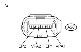 |
Measure the resistance according to the value(s) in the table below.
| Tester Connection | Switch Condition | Specified Condition |
| A28-6 (VPA1) - A28-5 (EP1) | Power switch off | 36.60 to 41.61 kΩ |
| A28-3 (VPA2) - A28-2 (EP2) | Power switch off | 36.60 to 41.61 kΩ |
| *a | Front view of wire harness connector (to Accelerator Pedal Sensor Assembly) |
Connect the accelerator pedal sensor assembly connector.
|
| ||||
| OK | ||
| ||
| ||
| 6.CHECK HARNESS AND CONNECTOR (POWER MANAGEMENT CONTROL ECU - ACCELERATOR PEDAL SENSOR) |
Disconnect connector A28 from the accelerator pedal sensor assembly.
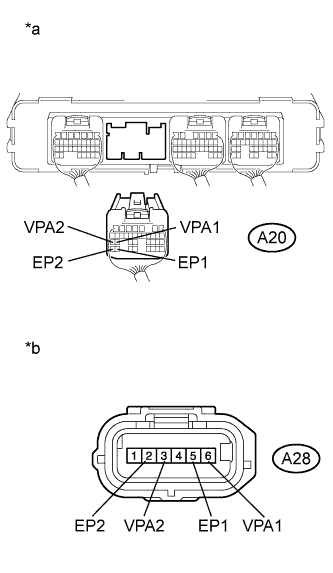 |
Disconnect connector A20 from the power management control ECU.
Turn the power switch on (IG).
Measure the voltage according to the value(s) in the table below.
| Tester Connection | Switch Condition | Specified Condition |
| A20-26 (VPA1) - Body ground | Power switch on (IG) | Below 1 V |
| A20-27 (VPA2) - Body ground | Power switch on (IG) | Below 1 V |
| A20-34 (EP1) - Body ground | Power switch on (IG) | Below 1 V |
| A20-35 (EP2) - Body ground | Power switch on (IG) | Below 1 V |
| *a | Rear view of wire harness connector (to Power Management Control ECU) |
| *b | Front view of wire harness connector (to Accelerator Pedal Sensor Assembly) |
Turn the power switch off.
Measure the resistance according to the value(s) in the table below.
| Tester Connection | Switch Condition | Specified Condition |
| A20-26 (VPA1) - A28-6 (VPA1) | Power switch off | Below 1 Ω |
| A20-34 (EP1) - A28-5 (EP1) | Power switch off | Below 1 Ω |
| A20-27 (VPA2) - A28-3 (VPA2) | Power switch off | Below 1 Ω |
| A20-35 (EP2) - A28-2 (EP2) | Power switch off | Below 1 Ω |
| Tester Connection | Switch Condition | Specified Condition |
| A20-26 (VPA1) or A28-6 (VPA1) - Body ground and other terminals | Power switch off | 10 kΩ or higher |
| A20-34 (EP1) or A28-5 (EP1) - Body ground and other terminals | Power switch off | 10 kΩ or higher |
| A20-27 (VPA2) or A28-3 (VPA2) - Body ground and other terminals | Power switch off | 10 kΩ or higher |
| A20-35 (EP2) or A28-2 (EP2) - Body ground and other terminals | Power switch off | 10 kΩ or higher |
Connect the power management control ECU connector.
Connect the accelerator pedal sensor assembly connector.
|
| ||||
| OK | ||
| ||
| ||
| 7.CHECK HARNESS AND CONNECTOR (POWER MANAGEMENT CONTROL ECU - ACCELERATOR PEDAL SENSOR) |
Disconnect connector A28 from the accelerator pedal sensor assembly.
Disconnect connector A20 from the power management control ECU.
Turn the power switch on (IG).
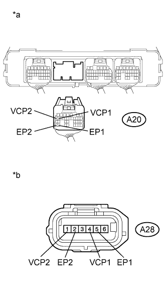 |
Measure the voltage according to the value(s) in the table below.
| Tester Connection | Switch Condition | Specified Condition |
| A20-18 (VCP1) - Body ground | Power switch on (IG) | Below 1 V |
| A20-34 (EP1) - Body ground | Power switch on (IG) | Below 1 V |
| A20-19 (VCP2) - Body ground | Power switch on (IG) | Below 1 V |
| A20-35 (EP2) - Body ground | Power switch on (IG) | Below 1 V |
| *a | Rear view of wire harness connector (to Power Management Control ECU) |
| *b | Front view of wire harness connector (to Accelerator Pedal Sensor Assembly) |
Turn the power switch off.
Measure the resistance according to the value(s) in the table below.
| Tester Connection | Switch Condition | Specified Condition |
| A20-18 (VCP1) - A28-4 (VCP1) | Power switch off | Below 1 Ω |
| A20-34 (EP1) - A28-5 (EP1) | Power switch off | Below 1 Ω |
| A20-19 (VCP2) - A28-1 (VCP2) | Power switch off | Below 1 Ω |
| A20-35 (EP2) - A28-2 (EP2) | Power switch off | Below 1 Ω |
| Tester Connection | Switch Condition | Specified Condition |
| A20-18 (VCP1) or A28-4 (VCP1) - Body ground and other terminals | Power switch off | 10 kΩ or higher |
| A20-34 (EP1) or A28-5 (EP1) - Body ground and other terminals | Power switch off | 10 kΩ or higher |
| A20-19 (VCP2) or A28-1 (VCP2) - Body ground and other terminals | Power switch off | 10 kΩ or higher |
| A20-35 (EP2) or A28-2 (EP2) - Body ground and other terminals | Power switch off | 10 kΩ or higher |
Connect the power management control ECU connector.
Connect the accelerator pedal sensor assembly connector.
|
| ||||
| OK | ||
| ||
| ||


