DTC P0A94-549 DC / DC Converter Performance |
| DTC No. | INF Code | DTC Detection Condition | Trouble Area |
| P0A94 | 549 | Boost converter overvoltage signal detection (overvoltage due to hybrid vehicle transaxle assembly malfunction) |
|
| 1.CHECK DTC OUTPUT (HYBRID CONTROL) |
Connect the intelligent tester to the DLC3.
Turn the power switch on (IG).
Enter the following menus: Powertrain / Hybrid Control / DTC.
Check if DTCs are output.
| Result | Proceed to |
| DTC P0A94-549 only is output. | A |
| Any of the following DTCs are also output. | B |
| DTC No. | Relevant Diagnosis |
| P0A1A (all INF codes)*1 | Generator Control Module |
| P0A1B (all INF codes)*1 | Drive Motor "A" Control Module |
| P0A1D (all INF codes)*1 | Hybrid Powertrain Control Module |
| P0A3F-243 | Drive Motor "A" Position Sensor Circuit |
| P0A40-500 | Drive Motor "A" Position Sensor Circuit Range / Performance |
| P0A41-245 | Drive Motor "A" Position Sensor Circuit Low |
| P0A4B-253 | Generator Position Sensor Circuit |
| P0A4C-513 | Generator Position Sensor Circuit Range / Performance |
| P0A4D-255 | Generator Position Sensor Circuit Low |
| P0A60 (all INF codes)*1 | Drive Motor "A" Phase V Current |
| P0A63 (all INF codes)*1 | Drive Motor "A" Phase W Current |
| P0A72 (all INF codes)*1 | Generator Phase V Current |
| P0A75 (all INF codes)*1 | Generator Phase W Current |
| P0A78-266, 267, 287, 505, 506, 586, 806, 807, 808 | Drive Motor "A" Inverter Performance |
| P0A7A-325, 517, 518, 809, 810, 811 | Generator Inverter Performance |
| P0A94-554, 555, 556, 564, 585, 587, 589, 590 | DC / DC Converter Performance |
| P0ADB-227 | Hybrid Battery Positive Contactor Control Circuit Low |
| P0ADC-226 | Hybrid Battery Positive Contactor Control Circuit High |
| P0ADF-229 | Hybrid Battery Negative Contactor Control Circuit Low |
| P0AE0-228 | Hybrid Battery Negative Contactor Control Circuit High |
| P0C76-523 | Hybrid Battery System Discharge Time Too Long |
| P3004-803 | Power Cable Malfunction |
Turn the power switch off.
|
| ||||
| A | |
 |
| 2.CHECK CONNECTOR CONNECTION CONDITION (INVERTER WITH CONVERTER ASSEMBLY CONNECTOR) |
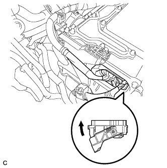 |
Check that the service plug grip is not installed.
Check the connection of the low voltage connector of the inverter with converter assembly.
|
| ||||
| OK | |
|
| 3.CHECK HARNESS AND CONNECTOR (INVERTER WITH CONVERTER ASSEMBLY - GENERATOR RESOLVER) |
Disconnect the low voltage connector D28 from the inverter with converter assembly.
Turn the power switch on (IG).
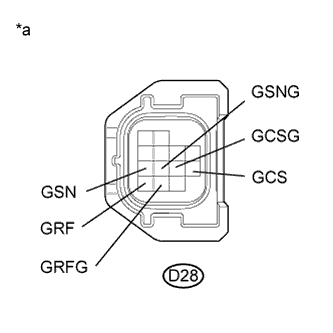 |
Measure the voltage according to the value(s) in the table below.
| Tester Connection | Switch Condition | Specified Condition |
| D28-11 (GRF) - Body ground | Power switch on (IG) | Below 1 V |
| D28-12 (GRFG) - Body ground | Power switch on (IG) | Below 1 V |
| D28-7 (GSN) - Body ground | Power switch on (IG) | Below 1 V |
| D28-8 (GSNG) - Body ground | Power switch on (IG) | Below 1 V |
| D28-10 (GCS) - Body ground | Power switch on (IG) | Below 1 V |
| D28-9 (GCSG) - Body ground | Power switch on (IG) | Below 1 V |
| *a | Front view of wire harness connector (to Inverter with Converter Assembly) |
Turn the power switch off.
Connect the low voltage connector from the inverter with converter assembly.
|
| ||||
| OK | |
|
| 4.CHECK GENERATOR RESOLVER |
Disconnect the low voltage connector D28 from the inverter with converter assembly.
|
Measure the resistance according to the value(s) in the table below.
| Tester Connection | Switch Condition | Specified Condition |
| D28-11 (GRF) - D28-12 (GRFG) | Power switch off | 7.1 to 21.6 Ω |
| D28-7 (GSN) - D28-8 (GSNG) | Power switch off | 13.7 to 34.5 Ω |
| D28-10 (GCS) - D28-9 (GCSG) | Power switch off | 12.8 to 32.4 Ω |
| Tester Connection | Switch Condition | Specified Condition |
| D28-11 (GRF) or D28-12 (GRFG) - Body ground and other terminals | Power switch off | 10 kΩ or higher |
| D28-7 (GSN) or D28-8 (GSNG) - Body ground and other terminals | Power switch off | 10 kΩ or higher |
| D28-10 (GCS) or D28-9 (GCSG) - Body ground and other terminals | Power switch off | 10 kΩ or higher |
| *a | Front view of wire harness connector (to Inverter with Converter Assembly) |
Connect the inverter with converter assembly connector.
|
| ||||
| OK | |
|
| 5.CHECK HARNESS AND CONNECTOR (INVERTER WITH CONVERTER ASSEMBLY - MOTOR RESOLVER) |
Disconnect the low voltage connector D28 from the inverter with converter assembly.
Turn the power switch on (IG).
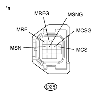 |
Measure the voltage according to the value(s) in the table below.
| Tester Connection | Switch Condition | Specified Condition |
| D28-1 (MRF) - Body ground | Power switch on (IG) | Below 1 V |
| D28-2 (MRFG) - Body ground | Power switch on (IG) | Below 1 V |
| D28-3 (MSN) - Body ground | Power switch on (IG) | Below 1 V |
| D28-4 (MSNG) - Body ground | Power switch on (IG) | Below 1 V |
| D28-6 (MCS) - Body ground | Power switch on (IG) | Below 1 V |
| D28-5 (MCSG) - Body ground | Power switch on (IG) | Below 1 V |
| *a | Front view of wire harness connector (to Inverter with Converter Assembly) |
Turn the power switch off.
Connect the inverter with converter assembly connector.
|
| ||||
| OK | |
|
| 6.CHECK MOTOR RESOLVER |
Disconnect the low voltage connector D28 from the inverter with converter assembly.
|
Measure the resistance according to the value(s) in the table below.
| Tester Connection | Switch Condition | Specified Condition |
| D28-1 (MRF) - D28-2 (MRFG) | Power switch off | 7.1 to 21.6 Ω |
| D28-3 (MSN) - D28-4 (MSNG) | Power switch off | 13.7 to 34.5 Ω |
| D28-6 (MCS) - D28-5 (MCSG) | Power switch off | 12.8 to 32.4 Ω |
| Tester Connection | Switch Condition | Specified Condition |
| D28-1 (MRF) or D28-2 (MRFG) - Body ground and other terminals | Power switch off | 10 kΩ or higher |
| D28-3 (MSN) or D28-4 (MSNG) - Body ground and other terminals | Power switch off | 10 kΩ or higher |
| D28-6 (MCS) or D28-5 (MCSG) - Body ground and other terminals | Power switch off | 10 kΩ or higher |
| *a | Front view of wire harness connector (to Inverter with Converter Assembly) |
Connect the inverter with converter assembly connector.
|
| ||||
| OK | |
|
| 7.CHECK CONNECTOR CONNECTION CONDITION (GENERATOR RESOLVER CONNECTOR) |
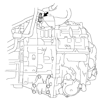 |
Check the connection of the generator resolver connector.
|
| ||||
| OK | |
|
| 8.CHECK CONNECTOR CONNECTION CONDITION (MOTOR RESOLVER CONNECTOR) |
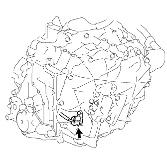 |
Check the connection of the motor resolver connector.
|
| ||||
| OK | ||
 | ||
| ||
| 9.CHECK CONNECTOR CONNECTION CONDITION (GENERATOR RESOLVER CONNECTOR) |
|
Check the connection of the generator resolver connector.
|
| ||||
| OK | |
|
| 10.CHECK HARNESS AND CONNECTOR (INVERTER WITH CONVERTER ASSEMBLY - GENERATOR RESOLVER) |
Disconnect the low voltage connector D28 from the inverter with converter assembly.
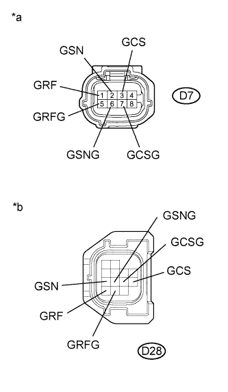 |
Disconnect the generator resolver connector.
Measure the resistance according to the value(s) in the table below.
| Tester Connection | Switch Condition | Specified Condition |
| D7-1 (GRF) - D28-11 (GRF) | Power switch off | Below 1 Ω |
| D7-5 (GRFG) - D28-12 (GRFG) | Power switch off | Below 1 Ω |
| D7-2 (GSN) - D28-7 (GSN) | Power switch off | Below 1 Ω |
| D7-6 (GSNG) - D28-8 (GSNG) | Power switch off | Below 1 Ω |
| D7-3 (GCS) - D28-10 (GCS) | Power switch off | Below 1 Ω |
| D7-7 (GCSG) - D28-9 (GCSG) | Power switch off | Below 1 Ω |
| Tester Connection | Switch Condition | Specified Condition |
| D7-1 (GRF) or D28-11 (GRF) - Body ground and other terminals | Power switch off | 10 kΩ or higher |
| D7-5 (GRFG) or D28-12 (GRFG) - Body ground and other terminals | Power switch off | 10 kΩ or higher |
| D7-2 (GSN) or D28-7 (GSN) - Body ground and other terminals | Power switch off | 10 kΩ or higher |
| D7-6 (GSNG) or D28-8 (GSNG) - Body ground and other terminals | Power switch off | 10 kΩ or higher |
| D7-3 (GCS) or D28-10 (GCS) - Body ground and other terminals | Power switch off | 10 kΩ or higher |
| D7-7 (GCSG) or D28-9 (GCSG) - Body ground and other terminals | Power switch off | 10 kΩ or higher |
| *a | Front view of wire harness connector (to Generator Resolver) |
| *b | Front view of wire harness connector (to Inverter with Converter Assembly) |
Connect the generator resolver connector.
Connect the inverter with converter assembly connector.
|
| ||||
| OK | ||
| ||
| ||
| 11.CHECK CONNECTOR CONNECTION CONDITION (MOTOR RESOLVER CONNECTOR) |
|
Check the connection of the motor resolver connector.
|
| ||||
| OK | |
|
| 12.CHECK HARNESS AND CONNECTOR (INVERTER WITH CONVERTER ASSEMBLY - MOTOR RESOLVER) |
Disconnect the low voltage connector D28 from the inverter with converter assembly.
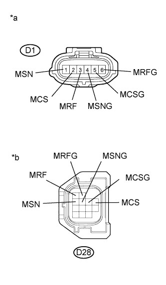 |
Disconnect the motor resolver connector.
Measure the resistance according to the value(s) in the table below.
| Tester Connection | Switch Condition | Specified Condition |
| D1-3 (MRF) - D28-1 (MRF) | Power switch off | Below 1 Ω |
| D1-6 (MRFG) - D28-2 (MRFG) | Power switch off | Below 1 Ω |
| D1-1 (MSN) - D28-3 (MSN) | Power switch off | Below 1 Ω |
| D1-4 (MSNG) - D28-4 (MSNG) | Power switch off | Below 1 Ω |
| D1-2 (MCS) - D28-6 (MCS) | Power switch off | Below 1 Ω |
| D1-5 (MCSG) - D28-5 (MCSG) | Power switch off | Below 1 Ω |
| Tester Connection | Switch Condition | Specified Condition |
| D1-3 (MRF) or D28-1 (MRF) - Body ground and other terminals | Power switch off | 10 kΩ or higher |
| D1-6 (MRFG) or D28-2 (MRFG) - Body ground and other terminals | Power switch off | 10 kΩ or higher |
| D1-1 (MSN) or D28-3 (MSN) - Body ground and other terminals | Power switch off | 10 kΩ or higher |
| D1-4 (MSNG) or D28-4 (MSNG) - Body ground and other terminals | Power switch off | 10 kΩ or higher |
| D1-2 (MCS) or D28-6 (MCS) - Body ground and other terminals | Power switch off | 10 kΩ or higher |
| D1-5 (MCSG) or D28-5 (MCSG) - Body ground and other terminals | Power switch off | 10 kΩ or higher |
| *a | Front view of wire harness connector (to Motor Resolver) |
| *b | Front view of wire harness connector (to Inverter with Converter Assembly) |
Connect the motor resolver connector.
Connect the inverter with converter assembly connector.
|
| ||||
| OK | ||
| ||
| ||


