DTC    P0AFC-123    Hybrid Battery Pack Sensor Module

for Preparation Click here


DESCRIPTION

  1. If the battery smart unit detects an internal malfunction, it sends an error signal to the power management control ECU. When the power management control ECU receives the error signal from the battery smart unit, the ECU warns the driver and performs fail-safe control.

DTC No.
DTC Detection Condition
Trouble Area
P0AFC-123
The power management control ECU receives an error signal from the battery smart unit.
  1. Battery smart unit
  2. Wire harness or connector
  3. IGCT No. 2 fuse

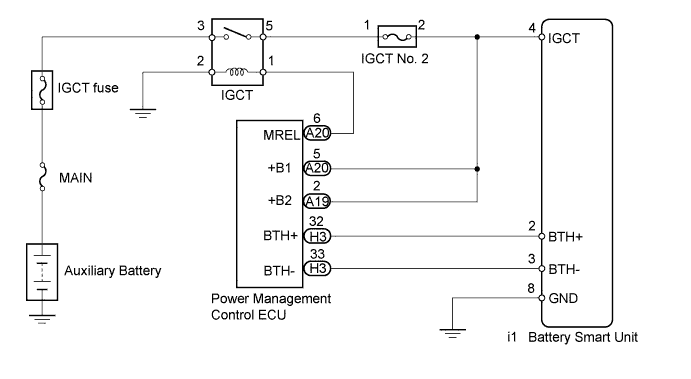
WIRING DIAGRAM


A250496E01


INSPECTION PROCEDURE

CAUTION:
  1. Before inspecting the high-voltage system, take safety precautions to prevent electrical shocks, such as wearing insulated gloves and removing the service plug grip. After removing the service plug grip, put it in your pocket to prevent other technicians from accidentally reconnecting it while you are working on the high-voltage system.
  2. After removing the service plug grip, wait for at least 10 minutes before touching any of the high-voltage connectors or terminals. After waiting for 10 minutes, check the voltage at the terminals in the inspection point in the inverter with converter assembly. The voltage should be 0 V before beginning work (Click here).

HINT:
  1. Waiting for at least 10 minutes is required to discharge the high-voltage capacitor inside the inverter with converter assembly.
  2. After completing repairs, restart the system (turn the power switch on (READY)) and recheck for DTCs (Click here).

NOTICE:
After turning the power switch off, waiting time may be required before disconnecting the cable from the negative (-) auxiliary battery terminal. Therefore, make sure to read the disconnecting the cable from the negative (-) auxiliary battery terminal notices before proceeding with work (Click here).

1.CHECK HARNESS AND CONNECTOR (IGCT VOLTAGE)

CAUTION:
Be sure to wear insulated gloves.

  1. Check that the service plug grip is not installed.
    NOTICE:
    After removing the service plug grip, do not turn the power switch on (READY), unless instructed by the repair manual because this may cause a malfunction.

  1. Turn the power switch on (IG).


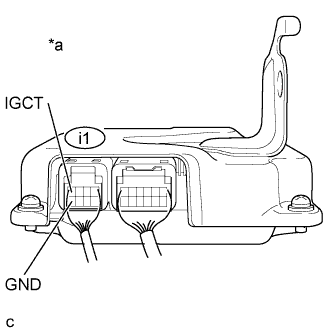
    A214447E18
  1. Measure the voltage according to the value(s) in the table below.

    Standard Voltage:
    Tester Connection
    Switch Condition
    Specified Condition
    i1-4 (IGCT) - i1-8 (GND)
    Power switch on (IG)
    11 to 14 V

    NOTICE:
    1. After removing the service plug grip, do not turn the power switch on (READY), unless instructed by the repair manual because this may cause a malfunction.
    2. Turning the power switch on (IG) with the service plug grip removed causes an interlock switch system DTC (P0A0D-350) to be set. Use the intelligent tester to clear the DTCs (Click here).

    Text in Illustration 
    *a
    Component with harness connected
    (Battery Smart Unit)

  1. Turn the power switch off.


NG
Go to step 2
OK

REPLACE BATTERY SMART UNIT (Click here)  

2.CHECK HARNESS AND CONNECTOR (GND - BODY GROUND)

CAUTION:
Be sure to wear insulated gloves.

  1. Check that the service plug grip is not installed.

    NOTICE:
    After removing the service plug grip, do not turn the power switch on (READY), unless instructed by the repair manual because this may cause a malfunction.


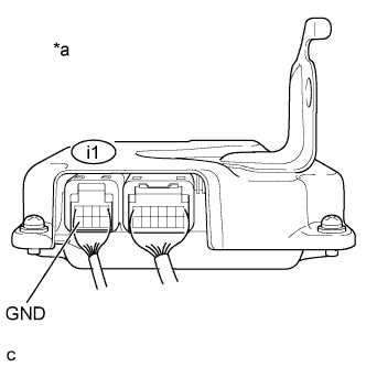
    A214447E15
  1. Measure the resistance according to the value(s) in the table below.

    Standard Resistance:
    Tester Connection
    Switch Condition
    Specified Condition
    i1-8 (GND) - Body ground
    Power switch off
    Below 1 Ω

    Text in Illustration 
    *a
    Rear view of wire harness connector
    (to Battery Smart Unit)


NG
REPAIR OR REPLACE HARNESS OR CONNECTOR
OK

REPLACE HARNESS OR CONNECTOR (IGCT NO. 2 FUSE - BATTERY SMART UNIT)