DTC P0AE2-773 Hybrid Battery Precharge Contactor Circuit Stuck Closed |
| DTC No. | INF Code | DTC Detection Condition | Trouble Area |
| P0AE2 | 773 | SMRP on the HV battery positive side stuck closed |
|
| 1.CHECK DTC OUTPUT (HYBRID CONTROL) |
Connect the intelligent tester to the DLC3.
Turn the power switch on (IG).
Enter the following menus: Powertrain / Hybrid Control / DTC.
Check if DTCs are output.
| Result | Proceed to |
| P0E2-773 only is output. | A |
| Any of the following DTCs are also output. | B |
| DTC No. | Relevant Diagnosis |
| P0A1A-151, 155, 156, 200, 658, 659, 791, 792, 793 | Generator Control Module |
| P0A1B-163, 164, 168, 193, 511, 512, 661, 786, 794, 795, 796 | Drive Motor "A" Control Module |
| P0A1D-148 | Hybrid Powertrain Control Module |
| P0A3F-243 | Drive Motor "A" Position Sensor Circuit |
| P0A40-500 | Drive Motor "A" Position Sensor Circuit Range/Performance |
| P0A41-245 | Drive Motor "A" Position Sensor Circuit Low |
| P0A4B-253 | Generator Position Sensor Circuit |
| P0A4C-513 | Generator Position Sensor Circuit Range/Performance |
| P0A4D-255 | Generator Position Sensor Circuit Low |
| P0A78-266, 267, 586 | Drive Motor "A" Inverter Performance |
| P0A94-442 | DC / DC Converter Performance |
| P0AE0-228 | Hybrid Battery Negative Contactor Control Circuit High |
| P0AA4-232 | Hybrid Battery Negative Contactor Circuit Stuck Closed |
| P0AE7-224 | Hybrid Battery Precharge Contactor Control Circuit High |
| P0C76-523 | Hybrid Battery System Discharge Time Too Long |
| P2511-149 | ECM/PCM Power Relay Sense Circuit Intermittent |
| P3004-132 | Power Cable Malfunction |
| P324E-788 | MG-ECU Power Relay Intermittent Circuit |
| U0110 (all INF codes)*1 | Lost Communication with Drive Motor Control Module |
Turn the power switch off.
|
| ||||
| A | |
 |
| 2.CHECK FREEZE FRAME DATA (HYBRID CONTROL) |
Connect the intelligent tester to the DLC3.
Turn the power switch on (IG).
Enter the following menus: Powertrain / Hybrid Control / DTC.
Read the freeze frame data of DTC P0AE2-773.
| Result | Proceed to |
| Pre-boost voltage (VL) is less than 60 V. | A |
| Post-boost voltage (VL) is 60 V or more. | B |
Turn the power switch off.
|
| ||||
| B | |
|
| 3.CHECK HYBRID BATTERY JUNCTION BLOCK ASSEMBLY |
Check that the service plug grip is not installed.
Remove the upper hybrid battery cover sub-assembly.
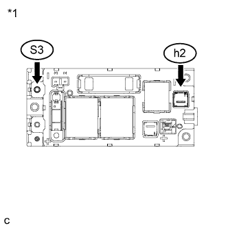 |
Measure the resistance according to the value(s) in the table below.
| Tester Connection | Switch Condition | Specified Condition |
| S3-1 (CEI) - h2-1 (-) | Power switch off | 10 kΩ or higher |
| *1 | Hybrid Battery Junction Block Assembly |
Install the upper hybrid battery cover sub-assembly.
|
| ||||
| OK | ||
 | ||
| ||

