DTC U029A-123 Lost Communication with Hybrid Battery Pack Sensor Module |
| DTC No. | DTC Detection Condition | Trouble Area |
| U029A-123 | Problem in serial communication between the battery smart unit and power management control ECU (1 trip detection) |
|
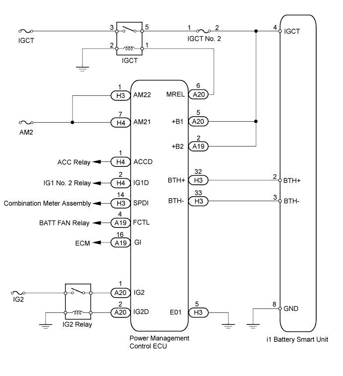
| 1.CHECK DTC OUTPUT (HV) |
Connect the intelligent tester to the DLC3.
Turn the power switch on (IG).
Enter the following menus: Powertrain / Hybrid Control / DTC.
Check for DTCs (Click here).
| Result | Proceed to |
| Only U029A-123 is output. | A |
| DTCs other than U029A-123 are also output. | B |
Disconnect the intelligent tester from the DLC3.
|
| ||||
| A | |
 |
| 2.CHECK HARNESS AND CONNECTOR (POWER MANAGEMENT CONTROL ECU - BATTERY SMART UNIT) |
Disconnect the cable from the negative (-) battery terminal of the auxiliary battery.
Check that the service plug grip is not installed.
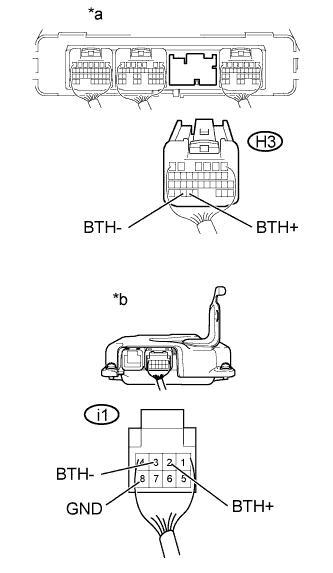
Disconnect connector H3 from the power management control ECU (Click here).
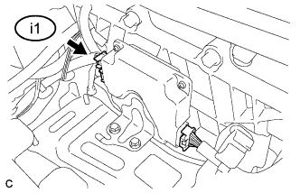 |
Disconnect connector i1 from the battery smart unit.
 |
Measure the resistance according to the value(s) in the table below.
| Tester Connection | Switch Condition | Specified Condition |
| H3-32 (BTH+) - i1-2 (BTH+) | Power switch off | Below 1 Ω |
| H3-33 (BTH-) - i1-3 (BTH-) | Power switch off | Below 1 Ω |
| i1-2 (BTH+) - i1-8 (GND) and Body ground | Power switch off | 10 kΩ or higher |
| i1-3 (BTH-) - i1-8 (GND) and Body ground | Power switch off | 10 kΩ or higher |
| *a | Rear view of wire harness connector (to Power Management Control ECU) |
| *b | Rear view of wire harness connector (to Battery Smart Unit) |
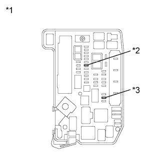 |
Remove the IGCT No. 2 fuse and AM2 fuse from the engine room junction block assembly.
| *1 | Engine Room Junction Block Assembly |
| *2 | AM2 Fuse |
| *3 | IGCT No. 2 Fuse |
Disconnect all connectors from the power management control ECU.
Measure the resistance according to the value(s) in the table below.
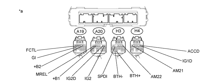
| Tester Connection | Switch Condition | Specified Condition |
| H3-32 (BTH+) - H4-7 (AM21) | Power switch off | 10 kΩ or higher |
| H3-32 (BTH+) - H3-1 (AM22) | Power switch off | 10 kΩ or higher |
| H3-32 (BTH+) - A19-2 (+B2) | Power switch off | 10 kΩ or higher |
| H3-32 (BTH+) - A20-5 (+B1) | Power switch off | 10 kΩ or higher |
| H3-32 (BTH+) - A20-6 (MREL) | Power switch off | 10 kΩ or higher |
| H3-32 (BTH+) - A20-1 (IG2) | Power switch off | 10 kΩ or higher |
| H3-32 (BTH+) - H4-1 (ACCD) | Power switch off | 10 kΩ or higher |
| H3-32 (BTH+) H4-2 (IG1D) | Power switch off | 10 kΩ or higher |
| H3-32 (BTH+) - A20-2 (IG2D) | Power switch off | 10 kΩ or higher |
| H3-32 (BTH+) - A19-4 (FCTL) | Power switch off | 10 kΩ or higher |
| H3-32 (BTH+) - H3-14 (SPDI) | Power switch off | 10 kΩ or higher |
| H3-32 (BTH+) - A19-16 (GI) | Power switch off | 10 kΩ or higher |
| H3-33 (BTH-) - H4-7 (AM21) | Power switch off | 10 kΩ or higher |
| H3-33 (BTH-) - H3-1 (AM22) | Power switch off | 10 kΩ or higher |
| H3-33 (BTH-) - A19-2 (+B2) | Power switch off | 10 kΩ or higher |
| H3-33 (BTH-) - A20-5 (+B1) | Power switch off | 10 kΩ or higher |
| H3-33 (BTH-) - A20-6 (MREL) | Power switch off | 10 kΩ or higher |
| H3-33 (BTH-) - A20-1 (IG2) | Power switch off | 10 kΩ or higher |
| H3-33 (BTH-) - H4-1 (ACCD) | Power switch off | 10 kΩ or higher |
| H3-33 (BTH-) - H4-2 (IG1D) | Power switch off | 10 kΩ or higher |
| H3-33 (BTH-) - A20-2 (IG2D) | Power switch off | 10 kΩ or higher |
| H3-33 (BTH-) - H3-14 (SPDI) | Power switch off | 10 kΩ or higher |
| H3-33 (BTH-) - A19-4 (FCTL) | Power switch off | 10 kΩ or higher |
| H3-33 (BTH-) - A19-16 (GI) | Power switch off | 10 kΩ or higher |
| *a | Rear view of wire harness connector (to Power Management Control ECU) | - | - |
Connect the cable to the negative (-) battery terminal of the auxiliary battery.
Connect the battery smart unit connector.
Connect the power management control ECU connectors (Click here).
|
| ||||
| OK | |
|
| 3.CHECK POWER MANAGEMENT CONTROL ECU |
Check that the service plug grip is not installed.
|
Disconnect connector i1 from the battery smart unit.
Turn the power switch on (IG).
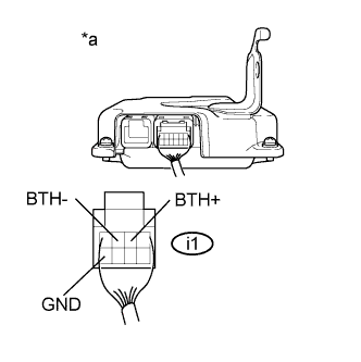 |
Measure the voltage according to the value(s) in the table below.
| Tester Connection | Switch Condition | Specified Condition |
| i1-2 (BTH+) - i1-8 (GND) | Power switch on (IG) | 2.3 to 2.7 V |
| i1-3 (BTH-) - i1-8 (GND) | Power switch on (IG) | 2.3 to 2.7 V |
| *a | Rear view of wire harness connector (to Battery Smart Unit) |
Turn the power switch off.
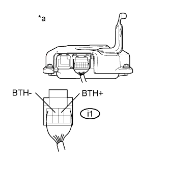 |
Measure the resistance according to the value(s) in the table below.
| Tester Connection | Switch Condition | Specified Condition |
| i1-2 (BTH+) - i1-3 (BTH-) | Power switch off | 4.4 to 5.4 kΩ |
| *a | Rear view of wire harness connector (to Battery Smart Unit) |
Connect the battery smart unit connector.
|
| ||||
| OK | ||
 | ||
| ||

