AIR CONDITIONING SYSTEM > TERMINALS OF ECU |
| AIR CONDITIONING AMPLIFIER ASSEMBLY |
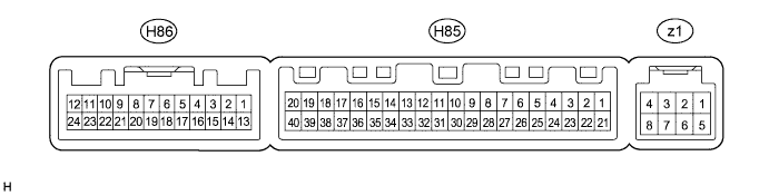
| Terminal No. (Symbol) | Wiring Color | Terminal Description | Condition | Specified Condition |
| H85-1 (IG+) - H85-14 (GND) | B - W-B | Power source (IG) | Power switch on (IG) | 11 to 14 V |
| Power switch off | Below 1 V | |||
| H85-5 (TAM) - H85-13 (SG-2) | BE - G | Ambient temperature sensor signal | Power switch on (IG) Ambient temperature: 25°C (77°F) | 1.35 to 1.75 V |
| Power switch on (IG) Ambient temperature: 40°C (104°F) | 0.9 to 1.2 V | |||
| H85-9 (PRE) - H85-13 (SG-2) | L - G | A/C pressure sensor signal | A/C system operating, Refrigerant pressure: Abnormal pressure (more than 3140 kPa (32.0 kgf/cm2, 455 psi)) | 4.88 V or higher |
| A/C system operating, Refrigerant pressure: Abnormal pressure (less than 196 kPa (2.0 kgf/cm2, 28 psi)) | Below 0.65 V | |||
| A/C system operating, Refrigerant pressure: Normal pressure (less than 3140 kPa (32.0 kgf/cm2, 455 psi) and more than 196 kPa (2.0 kgf/cm2, 28 psi)) | 0.65 to 4.88 V | |||
| H85-10 (S5-3) - H85-13 (SG-2) | B - G | Power supply for A/C pressure sensor | Power switch on (IG) A/C switch: on | 4.75 to 5.25 V |
| Power switch on (IG) A/C switch: off | Below 1 V | |||
| H85-11 (CANH) - H85-12 (CANL) | Y - BR | CAN communication system | CAN communication circuit | Pulse generation |
| H85-13 (SG-2) - Body ground | G - Body ground | Ground for A/C pressure sensor, ambient temperature sensor | Always | Below 1 V |
| H85-14 (GND) - Body ground | W-B - Body ground | Ground for main power supply | Always | Below 1 V |
| H85-15 (ECON) - H85-14 (GND) | R - W-B | Combination switch (ECO switch) signal | Power switch on (IG) Combination switch (ECO switch) off | 11 to 14 V |
| Power switch on (IG) Combination switch (ECO switch) on | Below 1 V | |||
| H85-16 (PTC3) - H85-14 (GND)*2 | BR - W-B | PTC heater operation signal | Engine is running (1250 rpm or higher) Temperature setting: MAX. HOT Ambient temperature: 10°C (50°F) or lower Engine coolant temperature: 65°C (149°F) or lower Light control switch off Blower switch on | 11 to 14 V |
| H85-18 (PTC1) - H85-14 (GND)*2 | W - W-B | PTC heater operation signal | Engine is running (1250 rpm or higher) Temperature setting: MAX. HOT Ambient temperature: 10°C (50°F) or lower Engine coolant temperature: 75°C (167°F) or lower Light control switch off Blower switch on | 11 to 14 V |
| H85-21 (B) - H85-14 (GND) | Y - W-B | Power source (Back-up) | Power switch off | 11 to 14 V |
| H85-23 (BLW) - H85-14 (GND) | W - W-B | Blower motor speed control signal | Power switch on (IG) Blower switch: LO | Pulse generation (See waveform 1) |
| H85-28 (RH) - H85-14 (GND)*1 | LG - W-B | Glass humidity sensor signal | Power switch on (IG) Humidity: 40% Cabin temperature: 25°C (77°F) | 2.09 V |
| Power switch on (IG) Humidity: 60% Cabin temperature: 25°C (77°F) | 2.81 V | |||
| H85-29 (TR) - H85-34 (SG-1) | B - W | Room temperature sensor signal | Power switch on (IG) Cabin temperature: 25°C (77°F) | 1.8 to 2.2 V |
| Power switch on (IG) Cabin temperature: 40°C (104°F) | 1.2 to 1.6 V | |||
| H85-31 (S5-4) - H85-14 (GND)*1 | V - W-B | Power supply for glass humidity sensor | Power switch off | Below 1 V |
| Power switch on (IG) | 4.5 to 5.5 V | |||
| H85-32 (TSP) - H85-14 (GND) | BR - W-B | Solar sensor signal (for front passenger side) | Power switch on (IG) Solar sensor subjected to electric light | 0.8 to 4.3 V |
| Power switch on (IG) Solar sensor covered with a cloth | Below 0.8 V | |||
| H85-33 (TSD) - H85-14 (GND) | B - W-B | Solar sensor signal (for driver side) | Power switch on (IG) Solar sensor subjected to electric light | 0.8 to 4.3 V |
| Power switch on (IG) Solar sensor covered with a cloth | Below 0.8 V | |||
| H85-34 (SG-1) - Body ground | W - Body ground | Ground for room temperature sensor | Always | Below 1 V |
| H85-35 (SG-4) - Body ground | W - Body ground | Ground for combination switch assembly (ECO switch) | Always | Below 1 V |
| H85-37 (LIN1) - H85-14 (GND) | V - W-B | LIN communication signal | Power switch on (IG) | Pulse generation |
| H85-38 (PTC2) - H85-14 (GND)*2 | B - W-B | PTC heater operation signal | Engine is running (1250 rpm or higher) Temperature setting: MAX. HOT Ambient temperature: 10°C (50°F) or lower Engine coolant temperature: 65°C (149°F) to 70°C (158°F) Light control switch off Blower switch on | 11 to 14 V |
| H86-7 (LBLO) - Body ground*1 | BR - Body ground | Ground for air conditioning thermistor assembly | Always | Below 1 V |
| H86-15 (TFG) - H85-14 (GND)*1 | GR - W-B | Glass temperature signal | Power switch on (IG) Glass temperature: 25°C (77°F) | 2.200 kΩ |
| H86-16 (TNG) - H85-14 (GND)*1 | SB - W-B | Glass surroundings signal | Power switch on (IG) Glass temperature: 25°C (77°F) | 2.200 kΩ |
| z1-2 (BUS G) - Body ground | - | Ground for BUS IC | Always | Below 1 V |
| z1-3 (BUS) - z1-2 (BUS G) | - | BUS IC control signal | Power switch on (IG) | Pulse generation |
| z1-4 (B BUS) - z1-2 (BUS G) | - | Power supply for BUS IC | Power switch off | 11 to 14 V |
| z1-5 (SGA) - Body ground | - | Ground for evaporator temperature sensor | Always | Below 1 V |
| z1-6 (TEA) - z1-5 (SGA) | - | A/C evaporator temperature sensor signal | Power switch on (IG) Evaporator temperature: 0°C (32°F) | 2.0 to 2.4 V |
| Power switch on (IG) Evaporator temperature: 15°C (59°F) | 1.4 to 1.8 V |
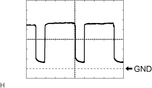 |
Waveform 1:
| Item | Content |
| Terminal No. | H85-23 (BLW) - H85-14 (GND) |
| Tool Setting | 1 V/DIV., 500 μs/DIV. |
| Vehicle Condition | Power switch on (IG) Blower switch: LO |
| CENTER CLUSTER MODULE CIRCUIT (AIR CONDITIONING CONTROL ASSEMBLY) |

| Terminal No. (Symbol) | Wiring Color | Terminal Description | Condition | Specified Condition |
| H80-1 (ACC) - Body ground | V - Body ground | Power source (ACC) | Power switch on (ACC) | 11 to 14 V |
| Power switch off | Below 1 V | |||
| H80-2 (IG+) - Body ground | B - Body ground | Power source (IG) | Power switch on (IG) | 11 to 14 V |
| Power switch off | Below 1 V | |||
| H80-4 (+B) - Body ground | R - Body ground | Power source (Back-up) | Power switch off | 11 to 14 V |
| H80-6 (ILL+) - Body ground | G - Body ground | Light control switch signal | Light control switch tail or head position | 11 to 14 V |
| Light control switch off | Below 1 V | |||
| H80-11 (LIN1) - Body ground | V - Body ground | LIN communication signal | Power switch on (IG) | Pulse generation |
| H80-16 (GND) - Body ground | W-B - Body ground | Ground for center cluster module circuit (air conditioning control assembly) | Always | Below 1 V |
| POWER MANAGEMENT CONTROL ECU (Click here) |
